


36
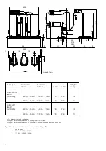
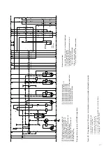
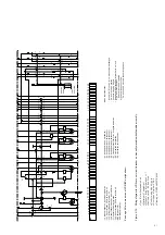
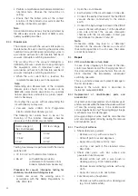
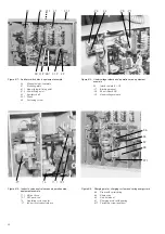
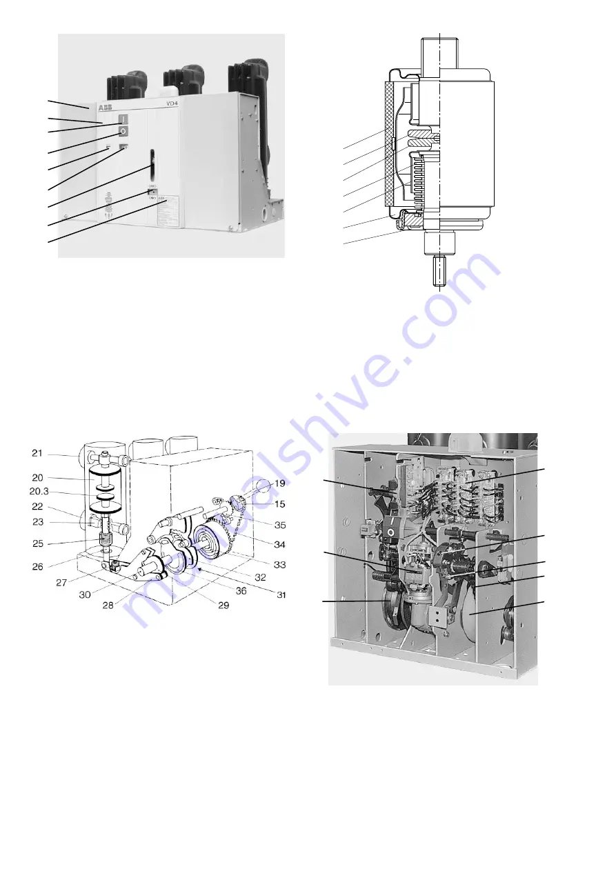
Figure 4/6: Basic structure of the stored-energy spring mechanism
15
Recess
19
Charging lever
20
Vacuum interrupter
20.3
Movable contact
21
Upper breaker terminal
22
Lower breaker terminal
23
Flexible connector
25
Contact force spring
26
Insulated coupling rod
27
Opening spring
28
Shift lever pair
29
Cam disk
30
Drive shaft
31
Release mechanism
32
Stop disk
33
Drum with spiral spring
34
Chain drive
35
Ratchet wheel
36
Left-hand control cam
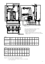
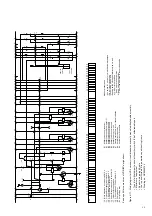
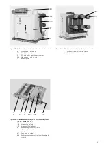
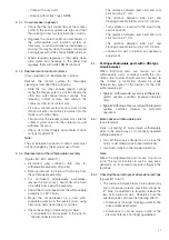
Figure 4/7: View of the stored-energy spring mechanism and
auxiliary equipment with the front plate removed
15
Recess for charging lever 19
31
Release and control mechanism on the drive shaft
33
Drum with spiral spring
34
Chain drive
35
Ratchet wheel
37
Charging motor
38
Release and control mechanism area
39
Auxiliary switch block
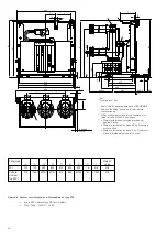
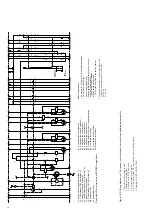
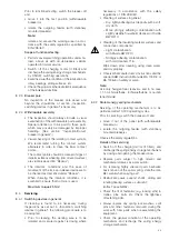
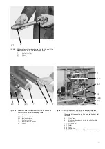
Figure 4/5: Partial section of a vacuum interrupter,
simplified schematic diagram
(Details vary according to the specified switching duties)
20.1
Insulator
20.2
Fixed contact
20.3
Movable contact
20.4
Metal bellows
20.5
Screen
20.6
Guide
20.7
Interrupter lid
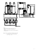
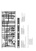
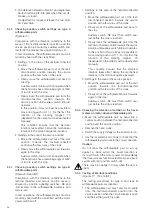
Figure 4/4: Circuit-breaker front with controls and annunciations
9.1 Mechanism enclosure
9.2 Front plate
11
ON push-button
12
OFF push-button
13
Mechanical position indicator
14
Mechanical operating cycle counter
15
Recess for charging lever 19
17
Rating plate
18
Mechanical charging condition indicator
20.1
20.2
20.3
20.4
20.5
20.7
20.6
9.1
9.2
11
12
14
13
15
18
17
38
31
39
15
35
33
34
37
Содержание VD4 Series
Страница 2: ......
Страница 55: ...ABB Connect ABB Connect ABB ABB ABB Connect iOS Android Windows 10...


