


42
54
55
58
51
52
53
32
61
61
Fig. 20a
Fig. 20b
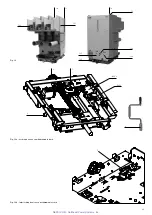
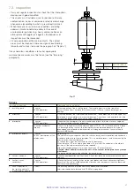
a) Mounting the adapters (fig. 20a)
The fuseholder (32) (fig. 20b) is preset to take fuses with fixing
centre distance of 553 mm. For smaller sizes, three adapters
are needed, as indicated below:
– adapter (51) for fuses with fixing centre distance
l = 235 mm
– adapter (52) for fuses with fixing centre distance
l = 305 mm
– adapter (53) for fuses with fixing centre distance
l = 454 mm.
Select the type of adapter, fix it onto the fuse on the striker
side by means of the grub screws (54), the cup springs (55)
and the short nuts (58). Mount the adapter with the extension,
with the cap facing the striker.
The same instructions are given in the Kit sheet put in the
adapter packing.
Only position the grub screws (54) as shown
in the drawing.
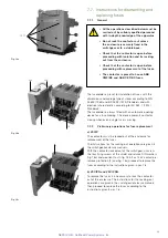
b) Mounting the fuses (fig. 20b)
Mount the fuses or the adapter (preassembled as indicated
in par. a) with the striker, (indicated by the arrow) facing the
opposite side to the one of the contactor tulips and fix them
by means of the screws (56) and the spring washers (57).
c) Dismantling the fuses
To dismantle the fuses and relative adapters, proceed in
reverse order to par. b) and a).
d) Assembling and dismantling the VSC/PN and VSC/PNG
contactor fuses
It is also possible to use BS fuses with double cartridge
connected in parallel in the VSC/PN and VSC/PNG contactors
(fig. 20c) and therefore in series with the contactor. The
assembly and dismantling operations are the same as what
is described in sections a) , b) and c) above, with the only
difference being to handle a pair of fuses per phase at the
same time (fig. 20c) connected by means of a suitable
adapter.
Striker side
Fig. 20c
NEPSI.COM - Northeast Power Systems. Inc.


