24
N. of pin
Connections
Abbr. of binary
outputs/inputs
Meaning of each pin (*)
Basic version
“Full option” version
-XDB10-1
Auxiliary power supply
–
Auxiliary power supply AC or DC (pole 1)
Auxiliary power supply AC or DC (pole 1)
-XDB10-2
Auxiliary power supply
–
Auxiliary power supply AC or DC (pole 2)
Auxiliary power supply AC or DC (pole 2)
-XDB10-3
Binary output n° 1
-PFG
Indication of unit ready and coil continuity
control (pole 1)
Indication of unit ready and coil continuity
control (pole 1)
-XDB10-4
Binary output n° 1
Indication of unit ready and coil continuity
control (pole 2)
Indication of unit ready and coil continuity
control (pole 2)
-XDB10-5
Binary output n° 2
-PFR
Not used
Indication of capacitor state (pole 2)
-XDB10-6
Binary output n° 2
Not used
Indication of capacitor state (pole 1)
-XDB10-7
Binary input n° 1
-SFC
Closing (pole 1)
Closing (pole 1)
-XDB10-8
Binary input n° 1
Closing (pole 2)
Closing (pole 2)
-XDB10-9
Binary input n° 2
-SFO
Opening (pole 1)
Opening (pole 1)
-XDB10-10
Binary input n° 2
Opening (pole 2)
Opening (pole 2)
-XDB10-11
Binary input n° 3
-SFL2
Undervoltage (pole 1)
Undervoltage (pole 1)
-XDB10-12
Binary input n° 3
Undervoltage (pole 2)
Undervoltage (pole 2)
(*) For availability, ask ABB.
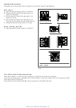
Connection of the auxiliary circuits
The cables to be used for connection of the auxiliary circuits
must have a rated voltage Uo/U of 450/750 V and be
insulated for 3 kV test.
Note:
before carrying out the test, disconnect the earthing
connection of the electronic feeder.
Also remember that the auxiliary circuits must be checked at
the maximum voltage of 2 kV for 1 second in accordance with
what is prescribed in the Standards.
The cross-section of the connection cables must not be less
than 1.5 mm
2
.
Connection of the contactor auxiliary circuits must be made
by means of the socket with terminal box mounted on the
front of the electronic card.
Outside, the wires must run through metallic pipes or ducts
suitably earthed.
Connection to be made by the customer (*)
Pins XDB10-1 and XDB10-2 must always be supplied, both
in the SCO and DCO version (also see par. 5.8.). The polarity
is not important since the internal circuits take both AC or DC
signals. For further details, consult the electric circuit diagram
enclosed with the apparatus.
NEPSI.COM - Northeast Power Systems. Inc.


