15
VSC7
VSC12
5.5. Overall dimensions
5.5.1. VSC fixed contactor
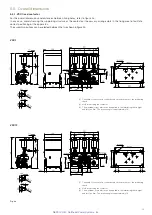
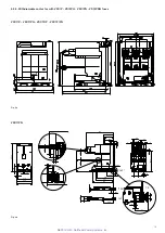
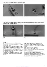
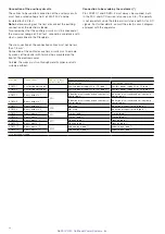
For the overall dimensions and distances between fixing holes, refer to figure 4a.
In any case, avoid stressing the supporting structure of the contactor: if necessary, arrange slots in the fixing area to facilitate
correct positioning of the apparatus.
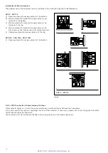
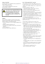
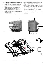
The assembly positions can be selected between the two shown in figure 4b.
Fig. 4a
(1) The width of the contactor varies based on the presence of the interfacing
shafts.
(2) Hole for earthing the contactor
(3) The maximum
torque
which can be applied to the interfacing shafts (right
and left) is 2 Nm. The rotation angle is approximately 10°.
(1) The width of the contactor varies based on the presence of the interfacing
shafts.
(2) Hole for earthing the contactor
(3) The maximum
torque
which can be applied to the interfacing shafts (right
and left) is 2 Nm. The rotation angle is approximately 10°.
NEPSI.COM - Northeast Power Systems. Inc.

