


31
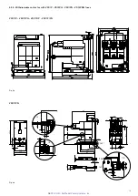
5.7.2. Contactor power supply
The contactor has been tested for all the auxiliary operating
voltages foreseen and indicated in the table:
Feeder 1-2 V c.c.
Feeder 3-4 V c.c. / V c.a. (50/60 Hz)
24
110
220
30
120
230
48
125
240
60
127
250
130
The contactor is, however, set with the operating voltage
defined in the order confirmation. The power supply voltage is
indicated on the contactor rating label.
The tolerances over the voltage values conform to what is
defined in the IEC 62271-106 Standard.
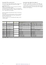
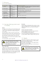
Basic board - Full option board
Ready DO1
-XDB10 (3-4)
Continuity control
Capacitor
voltage level and VSC
internal temperature
Anomaly
No anomaly
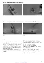
– After each operation
– Start-up
– Every 12 hours
Continuously
DO1 open
DO1
closed
Full option only
CBC DO2
-XDB10 (5-6)
Control of state of capacitor
efficiency
–
Anomaly
No anomaly
– Start-up
– Every 12 hours
–
DO2
open
DO2
closed
5.7.1. Diagnostics
Two types of electronic cards are available, “Basic board”
and “Full option”, differing from each other in the diagnostic
functions they have available.
Both have:
– coil continuity control connected to the card
– capacitor voltage level control.
The “Full option” card also makes the following available:
– control of the state of capacitor efficiency, which is
fundamental for correctly carrying out the opening and
closing operations
– checking and indicating the temperature inside the
contactor.
The alarms corresponding to the above functions are made
available to the user by means of two contacts (3-4 and 5-6)
of the -XDB10 terminal box.
The cards periodically carry out the controls without
preventing the opening and closing operations.
The table below indicates the functions available.
5.7.3. Coil continuity control (CCC) and temperature
monitoring
The unit checks actuator connection continuity so as to
reduce the risk of failure to operate following disconnection. It
also monitors the temperature of the board to reduce the risk
of operating beyond the board’s design limits.
This function is provided for both the basic MAC R2 board
and the “full option” version.
The test is performed:
– Every 2 minutes (irrespective of whether the apparatus is in
the open or closed condition)
– 15 seconds after starting
– After each operation
The test is not performed:
If the voltage of the external capacitance is less than 75 V
(“not ready” signal already given)
If the ambient temperature is less than -30° (“not ready” signal
already given)
An alarm signal is given by opening contact DO1 if errors
occur.
5.7.4. Capacitor ageing control (CBC)
The unit supervises bulk capacitor discharging so as to check
capacitor life.
The unit supervises main capacitor discharging so as to check
capacitor life.
This function is only available for the MAC R2 “full option”
version.
The test is performed:
– Every 12 hours when the apparatus is in the open condition.
– 15 seconds after starting.
– Two seconds after each opening operation if the contactor
has remained closed for 12 hours.
The test is not performed:
– If the voltage of the external capacitance is less than 75 V
(“not ready” signal already given).
– If the ambient temperature is less than -5° (“not ready”
signal already given).
The “not ready” state is signalled when the CBC function is
being performed and the function has priority over the closing
operation.
An alarm signal is given by opening contact DO2 if errors
occur.
NEPSI.COM - Northeast Power Systems. Inc.


