


36
TZIDC, TZIDC-110, TZIDC-120
DIGITAL POSITIONER | CI/TZIDC/110/120-EN REV. E
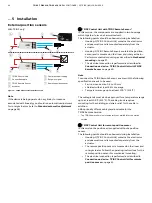
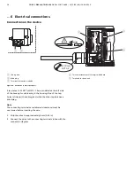
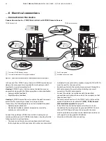
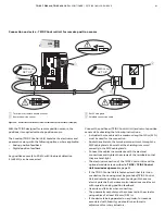
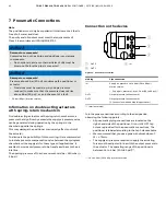
… 6 Electrical connections
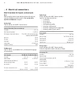
Electrical data for inputs and outputs
Note
When using the device in potentially explosive atmospheres,
note the additional connection data in
Use in potentially
explosive atmospheres
on page 5!
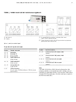
Analog input
Only for devices with HART® Communication.
Set point signal analog (two-wire technology)
Ter11
/
−
12
Nominal operating range
4 to 20 mA
Split range configuration between
20 to 100 % of the nominal operating
range can be parameterized
Maximum 50
mA
Minimum 3.6
mA
Starting at
3.8 mA
Load voltage
9.7 V at 20 mA
Impedance at 20 mA
485
Ω
Fieldbus input
Only for devices with PROFIBUS PA® or FOUNDATION Fieldbus®
Communication.
Bus Connection
PROFIBUS PA FOUNDATION fieldbus
Ter11
/
−
12
+11 /
−
12
Supply voltage
(Power feed from the Fieldbus)
9 to 32 V DC
9 to 32 V DC
Max. permissible voltage
35 V DC
35 V DC
Input Current
10.5 mA
11.5 mA
Current in the event of an error
15 mA
(10.5 mA + 4.5 mA)
15 mA
(11.5 mA + 3.5 mA)
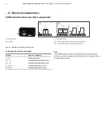
Digital input
Only for devices with HART® Communication.
Input for the following functions:
•
no function
•
move to 0 %
•
move to 100 %
• Hold
previous
position
• block local configuration
• block local configuration and operation
• block any access (local or via PC)
Binary input DI
Ter81
/
−
82
Supply voltage
24 V DC (12 to 30 V DC)
Input ‘logical 0’
0 to 5 V DC
Input ‘logical 1’
11 to 30 V DC
Input Current
Maximum 4 mA
Binary output
Only for devices with HART® Communication.
Output configurable as alarm output by software.
Binary output DO
Ter83
/
−
84
Supply voltage
(Control circuit in accordance with DIN
19234/NAMUR)
5 to 11 V DC
Output ‘logical 0’
> 0.35 mA to < 1.2 mA
Output ‘logical 1’
> 2.1 mA
Direction of action
Configurable
‘logical 0’ or ‘logical 1’


