


28
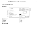
TZIDC, TZIDC-110, TZIDC-120
DIGITAL POSITIONER | CI/TZIDC/110/120-EN REV. E
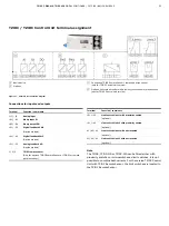
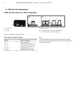
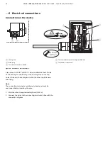
… 5 Installation
… Mechanical mounting
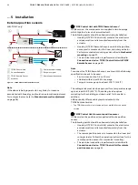
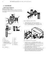
Mounting on linear actuators
For mounting on a linear actuator in accordance with DIN / IEC
534 (lateral mounting as per NAMUR), the following attachment
kit is available:
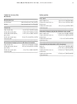
M10413-01
1
2
3
4
5
6
7
8
9
j
k
l
m
1
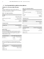
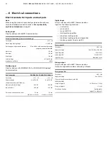
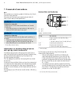
Screw
2
Washer
3
Mounting bracket
4
Lever with follower pin
(for mechanical stroke
10 to 35 mm (0.39 to 1.38 in) or
20 to 100 mm (0.79 to 3.94 in)
5
Washers
6
Screws
7
U-bolts
8
Washers
9
Nuts
j
Screws
k
Spring washers
l
Clamp plates
m
Follower guide
Figure 5: Attachment kit
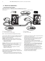
M10411-01
1
2
3
4
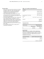
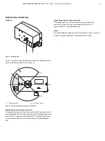
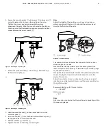
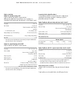
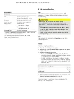
Figure 6: Attaching a follower guide to the actuator
1.
Tighten the screws so that they are hand-tight.
2.
Attach the follower guide
1
and clamp plates
2
with
screws
4
and spring washers
3
to the actuator stem.
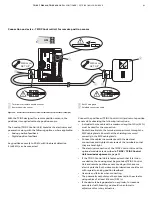
M10409-01
4
5
6
7
1
2
3
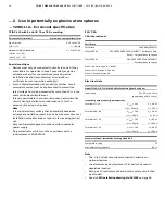
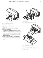
Figure 7: Mounting lever and bracket on the positioner
1.
Attach the lever
6
to the feedback shaft
5
of the
positioner (can only be mounted in one position due to the
cut shape of the feedback shaft).
2.
Using the arrow marks
4
, check whether the lever moves
within the operating range (between the arrows).
3.
Hand-tighten the screw
7
on the lever.
4.
Hold the prepared positioner (with the mount bracket
1
still
loose) on the actuator so that the follower pin for the lever
enters the follower guide to determine which tap holes on
the positioner must be used for the mount bracket.


