16
TZIDC, TZIDC-110, TZIDC-120
DIGITAL POSITIONER | CI/TZIDC/110/120-EN REV. E
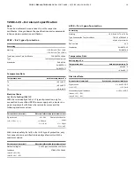
… 2 Use in potentially explosive atmospheres
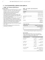
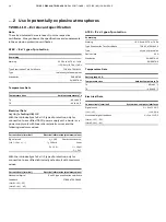
… TZIDC-110 – Ex relevant specification
TZIDC-110 with Ex nA IIC T6 or T4 Gc marking
Current circuit (terminal)
System bus, computer interfaces
Signal circuit
(+11 /
−
12)
U = 9 to 32 V DC
I = 10.5 mA
Mechanical digital feedback
(Limit1: +51 /
−
52)
(Limit2: +41 /
−
42)
U = 5 to 11 V DC
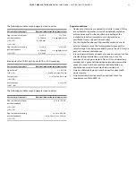
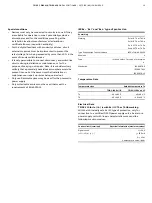
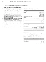
Special conditions
• Devices must only be connected to circuits in zone 2 if they
are suitable for operation in zone 2 potentially explosive
atmospheres and for the conditions prevailing at the
installation location (manufacturer's declaration or
certificate from an inspection authority).
• For the ‘digital feedback with proximity switches’ circuit,
external measures must be implemented to prevent the
rated voltage from being exceeded by more than 40 % in the
event of transient disturbances
• It is only permissible to connect, disconnect, and switch live
circuits during installation or maintenance, or for the
purpose of carrying out repairs.
Note
It is considered very unlikely that a potentially hazardous
atmosphere would be present in zone 2 at the same time that
installation or maintenance or repair work was being carried
out.
• Only non-flammable gases must be used for pneumatic
power supply.
• Only suited cable entries must be used that meet the
requirements of EN 60079-15.
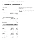
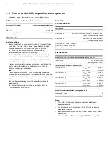
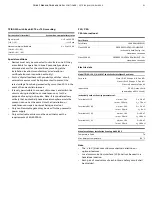
FM / CSA
CSA International
Certificate
Certificate
1649904 (LR 20312)
Class 2258 04
PROCESS CONTROL EQUIPMENT – Intrinsically Safe,
Entity – For Hazardous Locations
Class 2258 02
PROCESS CONTROL EQUIPMENT
–For Hazardous Locations
Class I, Div 2, Groups A, B, C and D;
Class II, Div 2, Groups E, F, and G,
Class III, Enclosure Type 4X:
Electrical data
Model TZIDC-110, P/N V18346-x032x2xx0x Intelligent Positioner
Input rated
32 V DC; max. 15 mA
(powered by a SELV circuit)
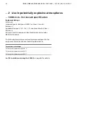
Intrinsically safe with entity parameters of:
Terminals 11 / 12
U
max.
= 24 V
I
max.
= 250 mA
C
i
= 2.8 nF
L
i
= 7.2 uH
Terminals 85 / 86
U
max.
= 30 V
I
max.
= 50 mA
C
i
= 3.8 nF
L
i
= 0 uH
Terminals 41 / 42
U
max.
= 16 V
I
max.
= 20 mA
C
i
= 60 nF
L
i
= 100 uH
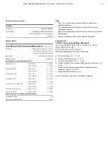
Terminals 51 / 52
U
max.
= 16 V
I
max.
= 20 mA
C
i
= 60 nF
L
i
= 100 uH
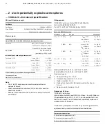
When installed per installation Drawing No 901265
Temperature code
T4
Max. Ambient temperature
85 °C
Note
• The ‘x’ in P/N denotes minor mechanical variations or
optional features.
• Local
communication
interface
(LCI) shall not be used in
hazardous location.
• Each pair of conductors of each intrinsic safety circuit shall
be shielded.
• See
also
FM installation drawing No. 901265
on page 56.

