


TTH300
HEAD-MOUNT TEMPERATURE TRANSMITTER | OI/TTH300-EN REV. G
29
9
Commissioning
General
In case of corresponding order the transmitter is ready for
operation after mounting and installation of the connections.
The parameters are set at the factory.
The connected lines must be checked for firm seating. Only
firmly seated lines ensure full functionality.
Hardware settings
on page 32
Checks prior to commissioning
The following points must be checked before commissioning the
device:
• Correct wiring in accordance with
Electrical connections
on page 21.
• The ambient conditions must correspond to the
information given on the name plate and in the data
sheet.
Communication
HART® Communication
Note
The HART® protocol is an unsecured protocol, as such the
intended application should be assessed to ensure that these
protocols are suitable before implementation.
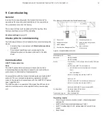
Communication with the transmitter takes place using the HART
protocol. The communication signal is modulated onto both
wires of the signal line in accordance with the HART FSK ‘Physical
Layer’ specification.
The HART modem is connected at the signal line of the current
output via which power is also supplied via the power supply
unit.
The device is listed with the FieldComm Group.
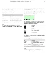
1
Transmitter
2
Handheld terminal
3
HART® modem
4
PC with Asset Management Tool
5
Grounding (optional)
6
Power supply unit (process
interface)
R
B
load resistance
(if necessary)
Figure 19: Example for HART® connection
Manufacturer ID
0x1A
Device ID
HART 5: 0x000B,
HART 7: 0x1A0B
Profile
From SW-Rev. 3.00 (corresponds to HW-Rev. 2.00 and
higher):
HART 5.9 and HART 7.6, switchable via
• HMI LCD indicator with configuration function
• Tools
• HART commands
Default, if nothing else ordered: HART 7.6.
SW-Rev. 1.03:
HART 5.1 and HART 7, switchable via DIP switch.
Default, if nothing else ordered: HART 5.1.
SW-Rev. 1.01.08: HART 5.1, previously HART 5.
Configuration
On device using LCD indicator
DTM, EDD, FDI (FIM)
Transmission signal
BELL Standard 202
Operating modes
• Point-to-point communication mode – standard (general
address 0)
• HART 5: Multidrop mode (addressing 1 to 15)
• HART 7: Addressing 0 to 63, independent of current loop
mode
• Burst Mode


