63/72
TLE Series 625 to 1000 PurePulse™ UL S2
UPS Installation Guide / REV-B
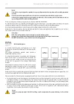
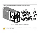
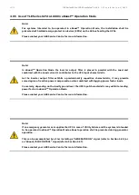
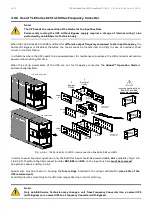
Note!
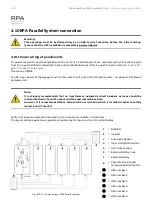
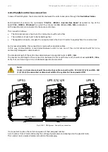
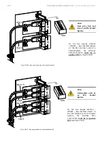
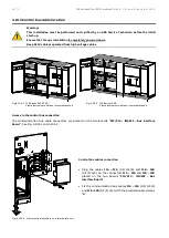
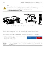
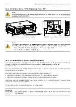
To operationalize this function, in case that the UPS was provided with one or more cards “P4 -
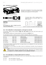
Customer Interface” (max. 3 - see Chapter 5), there must be on each card the following:
- Remove the cable short-circuiting terminals X2 / 1, 2 (see Fig. 4.11-3).
- Remove the Jumper JP2 (see Fig. 4.11-3).
Fig. 4.11-3 X2 terminal block and Jumper JP2 on the Customer Interface Board
When the “EPO - Emergency Power Off” has been activated, the system must be restored as follows:
•
Realize the push-button
“EPO - Emergency Power Off”
(contact on XA / EPO-1, EPO-2 is closed again).
•
Perform the “Inverter OFF” command from the screen:
Commands 1 / Inverter /
OFF
.
(see User Manual to Section 6.5).
In case of a Parallel System perform the “Inverter OFF” command from the screen “Commands
1 / Inverter / OFF” of each unit connected on the Parallel Bus and having its switch “Q1 - UPS
Output” closed.
CNT_Con
nectivity r
ack_X2-EP
O_ABB_0
1
16
15
4
19
18
17
20
9
8
7
6
5
14
13
12
3
2
1
22
11
2
1
21
10
X2
SNMP car
d
Customer i
nterface
1
2
8
19
21
22
20
10
11
9
17
18
16
15
7
6
5
4
12
14
13
3
2
1
X1
X2
J1
TLE
S_
16
0-
40
0_
S2
_C
us
to
m
er i
nt
erf
ac
e-
JP
2_
01
IM0171
C
U
ST
O
M
ER
IN
TE
R
FAC
E
JP2
X1
X2
J1
JP2
CUSTOMER INTERFACE

