13
Switchgroups
SGF6…8
(modified 96-02)
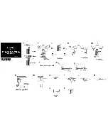
Using the different start and operation signals as
autoreclose start initiation signals AR1, AR2 or
AR3. The signal selection possibilities are shown
in Fig. 4 below.
In the figure the start and operate signals of the
different protection stages are connected to the
desired autoreclose start line AR1, AR2 or AR3,
for instance, by encircling the signal crossing
point. The numbers of the different switches
and their weight factors are marked near the
crossing points. The checksums for the different
switch groups are obtained by adding the weight
factors of the selected switches.
Switches SGF6/7…8 and SGF7/7…8 are not
in use.
Fig. 4. Selection matrix for the autoreclose initiation signals
1
(1)
2
(2)
3
(4)
4
(8)
5
(16)
6
(32)
1
(1)
3
(4)
5
(16)
7
(64)
2
(2)
4
(8)
6
(32)
8
(128)
AR1
AR3
Autoreclose
initiating signal
AR2
1
= switchnumber
(1)
= weighting factor
Checksum
(factory setting)
∑
SGF6 =
(
∑
= 0)
∑
SGF7 =
(
∑
= 0)
∑
SGF8 =
(
∑
= 0)
SGF6
1
(1)
1
(1)
2
(2)
3
(4)
4
(8)
5
(16)
6
(32)
I>
t>
I>>
t>>
I>>>
t>>>
I >
t >
I >>
t >>
Operation stage
0
0
0
0
SGF7
SGF6
SGF8
SGF8
SGF6 = switchgroup
Содержание SPAA 341 C /E351
Страница 130: ......


