ABB RMC-100 Скачать руководство пользователя страница 31


2105551-001 rev. AC | 

31


10 Troubleshooting 

10.1  Visual alarm and status codes 

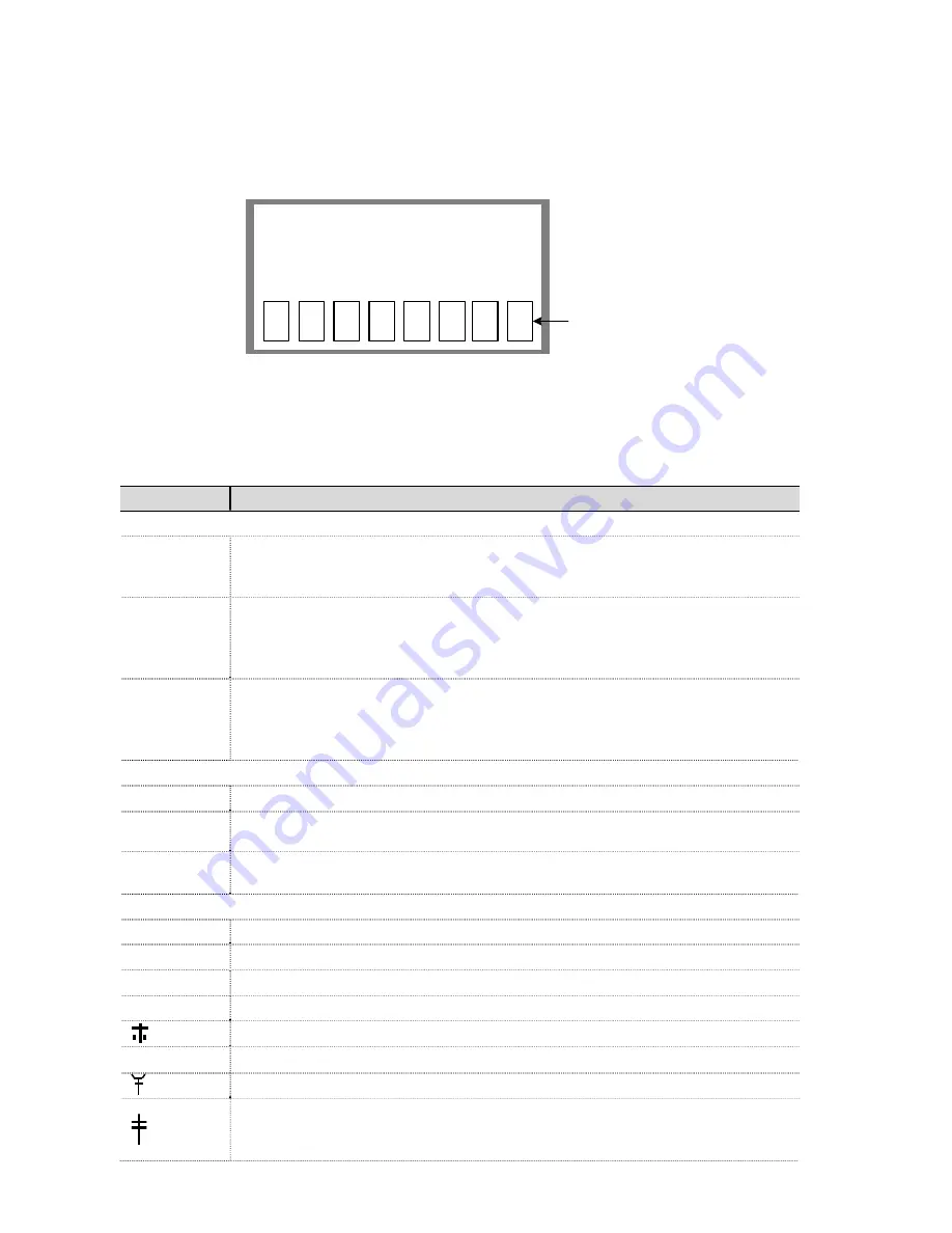
After powering on, observe the LCD display. System alarms may display and 
indicate a condition to be resolved (Figure 28). 

Annunciators

DATE/TIME

02/28/16 13:00:26

1

u n

C

L


Figure 28: LCD display 

Table 15 provides a description of the alarms and status codes. The alarms provide 
a brief summary of the action to resolve the condition. 

Table 15: Alarms and status codes 

Indicator 

Description and action 

System 

(Blank LCD) 

No annunciators or nothing on the display. No power to the controller. 
Action: Check the cable connections and check the voltage. Make a local 
connection with RMC and PCCU. 

LL 

Low Lithium Battery Alarm. When LL (low lithium) displays, the lithium 
battery voltage is below 2.5 Vdc. If lithium battery voltage is above 2.5 Vdc, 
LL appears shaded. A new lithium battery measures approximately 3.6 Vdc. 
Action: Replace the lithium battery. 

LC 

Low Charger. Displayed if the battery charging voltage is (+) 0.4 Vdc or is 
less than or equal to battery voltage. If (+) 0.4 Vdc battery charging voltage is 
greater than battery voltage, LC is shaded. 
Action: Check the cable connections and check the power source. 

Display application 

A number represents the Display Group number currently displayed. 


The displayed item’s value is above the Data High Limit value specified on 
the Display Item Setup screen. 


The displayed item’s value is below the Data Low Limit value specified on 
the Display Item Setup screen. 

Communication protocols 


Transmitting data: sending a response 


Receiving data: processing a response 

Nak: Negative acknowledgement with packet list 

Acknowledgement: positive acknowledge of receipt of request 


Waiting for Acknowledgement; waiting for response after transmission 

? Exception 

alarm 

processing 


ID Recognized: The ID has been recognized but is waiting for “Sync” 


Listen Cycle: flashes if this remote port is active and running Totalflow 
Remote Protocol. Flashes in sync with listening cycle that occurs at 1, 2 or 4 
second intervals. 

Содержание RMC-100

Страница 1: ...Modular Controller 100 will be referred to as the RMC or the controller unless otherwise indicated WARNING Bodily injury equipment damage Although there may be alternate methods of installation and co...

Страница 2: ...information Although ABB provides functionality testing on the products and updates that it releases the customer should institute its own testing program for any product updates or other major system...

Страница 3: ...TION Property damage minor injury This symbol in conjunction with the signal word CAUTION indicates a potentially dangerous situation Failure to observe this safety information may result in minor or...

Страница 4: ...e rated at least Type 3R according to the environment For Class I Zone 2 installations the RMC 100 shall be installed inside an enclosure tested for IP54 in accordance with IEC 60529 and IEC 60079 15...

Страница 5: ...If a solar panel is used decide where and how to install the solar panel outdoors For optimum charging avoid placing the solar panel where it will be in shadows any part of the day 2 5 Wiring require...

Страница 6: ...re powering the RMC DANGER Damage to health risk to life property damage Allowing the RMC components to make contact with a non insulated tool or without a proper grounding device could create a stati...

Страница 7: ...ser Manual 4 3 Wiring COMM ports Wire the RMC COMM ports to communicate with and power external devices Wiring for communication depends on the type of serial interface required by the device Wiring f...

Страница 8: ...section CAUTION Equipment damage An external device can be powered from pin 1 VOUT or pin 3 Sw VOUT on both COMM1 and COMM2 The output voltage at these pins is dependent upon the external power suppl...

Страница 9: ...n is dependent upon the external power supply connected to the CHARGER EXT PWR port Before connecting to these pins ensure that the external device is compatible with the input voltage at the CHARGER...

Страница 10: ...3 GND Input ground 2 1 PWR Power 4 1 PWR Power 2 AI Input signal 2 AI Input signal 3 GND Input ground 3 GND Input ground AI 1 2 3 4 1 2 3 1 2 3 1 2 3 1 2 3 Figure 3 Analog input pinouts 4 4 2 Analog o...

Страница 11: ...ignal DI DO 2 5 1 SIG Signal DI DO 5 2 GND ground 2 GND ground 3 1 SIG Signal DI DO 3 6 1 SIG Signal DI DO 6 2 GND ground 2 GND ground DI DO 1 2 3 4 5 6 1 2 1 2 1 2 1 2 1 2 1 2 Figure 6 Digital I O pi...

Страница 12: ...s 1 Attach the TFIO module to the DIN rail 2 Attach the TFIO interface cable to the first TFIO module 3 Attach the next TFIO module to the DIN rail 4 Position it beside the previously attached module...

Страница 13: ...Before connecting to these pins make sure that the external device is compatible with the input voltage at the CHARGER EXT PWR port Table 8 TFIO valve control interface module M2 J1 J2 J3 J4 1 POINT 1...

Страница 14: ...1 J Wht K Yel TC2 J Wht K Yel TC3 J Wht K Yel TC4 J Wht K Yel 3 TC1 Red TC2 Red TC3 Red TC4 Red 4 Shield Shield Shield Shield Table 13 TFIO RTD module M2 J1 J2 J3 J4 1 OUT OUT OUT OUT 2 3 4 IN IN IN I...

Страница 15: ...ing of the super capacitor Once the capacitor is fully charged the boot time is considerably less IMPORTANT NOTE In the event of a loss of power or reset the charged super capacitor prevents the suppl...

Страница 16: ...gure 8 Battery port 3 Confirm that the battery is supplying power to the RMC by observing the power on sequence information scrolling on the LCD see details in section 5 1 Power on sequence When the D...

Страница 17: ...e solar panel or alternate charger cable to the RMC before the battery is connected to the BAT port Figure 8 Battery port To connect the solar panel charger adapt instructions if connecting to a NEC C...

Страница 18: ...EXT PWR Figure 10 External power supply connection 3 Apply power to the external power supply 4 Confirm that the RMC is receiving power by observing the power on sequence information scrolling on the...

Страница 19: ...2 are not compatible It is assumed that PCCU32 is already installed in the PC or laptop used to connect to the controller To download the latest PCCU32 version see the Additional Information section F...

Страница 20: ...he computer USB port that the cable is connected to 7 Click Close 8 On the PCCU32 tool bar click Entry to connect to the device When the connection is successful the PCCU32 Entry screen displays 9 If...

Страница 21: ...e ID Location 24 digit alphanumeric The location identifier describes the location such as the county name or a road number Not mandatory Date Time MM DD YYYY HH MM SS 24 hour clock Date and time must...

Страница 22: ...en The security codes cannot be configured if the status is on 4 Type a four digit security code for Security Code Level 1 read only access 5 Type a four digit security code for Security Code Level 2...

Страница 23: ...rator slash dash or period 4 Select the preferred Time Separator colon or period 5 Click Send to save all of the station settings 7 Configuring communications 7 1 Configuring the COMM ports The config...

Страница 24: ...identify the port 10 Configure the Serial port settings to match the settings of the external device IMPORTANT NOTES The Interface setting for a modem is RS 232 Modem If the protocol selected in the...

Страница 25: ...he XMV Interface is chosen to support this type of connection Figure 19 Serial port configuration to connect XMVs Figure 20 provides a communication configuration example to connect equipment for remo...

Страница 26: ...ynamic addressing change the Enable DHCP field to Yes e If using static addresses type each of the parameters IP Address Default Gateway and Subnet Mask f Click Send An Information box displays a mess...

Страница 27: ...input configuration The analog input configuration consists of setting the AI to support the specific type measurement and operating range of the external device To reflect the external device s AI va...

Страница 28: ...libration 1 Select I O System on the navigation tree 2 Select the Analog Output tab Figure 24 Figure 24 Analog output configuration 3 Enter the AO percentage or the engineering units number 4 Click Se...

Страница 29: ...ue 5 Click Send 8 5 Pulse input configuration Each pulse input has a debounce filter Without debounce the PI operates at a frequency range of 0 to 20 kHz With debounce the frequency range is 0 to 100...

Страница 30: ...sabled by default To verify or enable communication with TFIO modules 1 On the navigation tree under the I O System a If modules were installed in TFIO A select TFIO A Modules Figure 27 The TFIO Modul...

Страница 31: ...thium battery LC Low Charger Displayed if the battery charging voltage is 0 4 Vdc or is less than or equal to battery voltage If 0 4 Vdc battery charging voltage is greater than battery voltage LC is...

Страница 32: ...ing Close signal is being sent to the valve actuator Valve RMC override conditions met DP SP override set point or Low Battery LL Local Lock out is initiated Measurement application H Hold displayed w...

Страница 33: ...2105551 001 rev AC 33 Notes...

Страница 34: ...34 2105551 001 rev AC This page left intentionally blank...

Страница 35: ...2105551 001 rev AC 35 This page left intentionally blank...

Страница 36: ...is document The original US English version of this manual shall be deemed the only valid version Translated versions in any other language shall be maintained as accurately as possible Should any dis...

Отзывы: