


2105551-001 rev. AC |
13
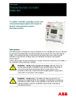
Figure 7 shows the side view of a TFIO module and its pinouts.
Side View
Pins
M2
Figure 7: TFIO module
Table 8 to 13 identify the wiring pins for the TFIO M2 modules used with the RMC.
The wiring pins are the same for legacy TFIO modules.
CAUTION – Equipment damage.
The output voltage at the following
pins is dependent upon the external power supply connected to the
CHARGER/EXT PWR port:
J2-1, J4-1 and J4-3 (Table 8) and J1-1, J2-1, J3-1, J4-1 (Table 9)
Before connecting to these pins, make sure that the external device is
compatible with the input voltage at the CHARGER/EXT PWR port.
Table 8: TFIO valve control interface module (M2)
J1
J2
J3
J4
1 POINT 1 SIG
AO Vdc source
POINT 3 SIG
POINT 5 SIG
2 POINT 1 GND
AO Isink
POINT 3 GND
POINT 6 SIG
3 POINT 2 SIG
AO Isource
POINT 4 SIG
POINT 7 SIG
4 POINT 2 GND
AO Vdc common
POINT 4 GND
POINT 8 SIG
Table 9: TFIO analog output (4-20 mA) module (M2)
J1
J2
J3
J4
1 AO1 Vdc source
AO2 Vdc source
AO3 Vdc source
AO4 Vdc source
2 AO1 Isink
AO2 Isink
AO3 Isink
AO4 Isink
3 AO1 Isource
AO2 Isource
AO3 Isource
AO4 Isource
4 AO1 Vdc common
AO2 Vdc common
AO3 Vdc common
AO4 Vdc common
Содержание RMC-100
Страница 33: ...2105551 001 rev AC 33 Notes...
Страница 34: ...34 2105551 001 rev AC This page left intentionally blank...
Страница 35: ...2105551 001 rev AC 35 This page left intentionally blank...


