


1.
Apply voltages U-Line (for example) = 100%
GblBaseSelLine and U-Bus = 100%
GblBaseSelBus, with a phase difference equal to 0 degrees and a frequency difference
lower than
FreqDiffA and FreqDiffM.
2.
Check that the AUTOSYOK and MANSYOK outputs are activated.
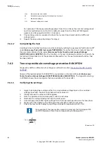
The test can be repeated with other phase difference values to verify that the function
operates for values lower than the set ones,
PhaseDiffM and PhaseDiffA. By changing the
phase angle on the voltage connected to U-Bus, between ± dφ degrees, the user can
check that the two outputs are activated for a phase difference lower than the set value.
It should not operate for other values. See figure
.
+d
j
-d
j
U-Bus
U-Line operation
U-Bus
No operation
en05000551.vsd
IEC05000551 V1 EN-US
Figure 16: Test of phase difference
3.
Change the phase angle bdφ and -dφ and verify that the two outputs are
activated for phase differences between these values but not for phase differences
outside, see figure
Testing the frequency difference
M2377-232 v6
The frequency difference test should verify that operation is achieved when the
FreqDiffA and
FreqDiffM frequency difference is lower than the set value for manual and auto synchronizing
check,
FreqDiffA and FreqDiffM respectively and that operation is blocked when the frequency
difference is greater.
Test with frequency difference = 0 mHz
Test with a frequency difference outside the set limits for manual and auto synchronizing
check respectively.
1.
Apply voltages U-Line equal to 100%
GblBaseSelLine and U-Bus equal to 100%
GblBaseSelBus, with a frequency difference equal to 0 mHz and a phase difference lower
than the set value.
2.
Check that the AUTOSYOK and MANSYOK outputs are activated.
3.
Apply voltage to the U-Line equal to 100%
GblBaseSelLine with a frequency equal to 50
Hz and voltage U-Bus equal to 100%
GblBaseSelBus, with a frequency outside the set
limit.
4.
Check that the two outputs are not activated. The test can be repeated with different
frequency values to verify that the function operates for values lower than the set ones. If
a modern test set is used, the frequency can be changed continuously.
Testing the reference voltage
M2377-249 v5
1.
Use the same basic test connection as in figure
.
Section 7
1MRK 505 293-UEN B
Testing functionality
82
Breaker protection REQ650
Commissioning manual
© Copyright 2013 ABB. All rights reserved
Содержание REQ650 1.3 IEC
Страница 1: ...Relion 650 SERIES Breaker protection REQ650 Version 1 3 IEC Commissioning manual ...
Страница 2: ......
Страница 12: ...6 ...
Страница 20: ...14 ...
Страница 28: ...22 ...
Страница 40: ...34 ...
Страница 42: ...36 ...
Страница 116: ...110 ...
Страница 123: ...117 ...