


8.
Set the measured current (fault current) in same phase to about 90% of the set operating
current
IP>. Switch off the current.
9.
Switch on the fault current and wait longer than the set value
tOper.
No TRIP signal should appear.
10. Switch off the fault current.
7.3.13.2
Completing the test
SEMOD175021-42 v4
Continue to test another function or end the testing by setting the parameter
TestMode to Off
under Main menu/Tests/IED test mode/TESTMODE:1. If another function is tested, then set
the parameter
Blocked to No under Main menu/Tests/Function test modes/Current/
BRCPTOC(46,lub)/BRCPTOC:X for the function, or for each individual function in a chain, to be
tested next. Remember to set the parameter
Blocked to Yes, for each individual function that
has been tested.
7.3.14
Directional underpower protection GUPPDUP
SEMOD175027-3 v5.1.1
Prepare the IED for verification of settings as outlined in section
Values of the logical signals for GUPPDUP are available on the local HMI under Main menu/
Tests/Function status/Current/GUPPDUP(37,P<)/GUPPDUP:1. The Signal Monitoring in
PCM600 shows the same signals that are available on the local HMI.
7.3.14.1
Verifying the settings
SEMOD175027-7 v7
The underpower protection shall be set to values according to the real set values to be used.
The test is made by means of injection of voltage and current where the amplitude of both
current and voltage and the phase angle between the voltage and current can be controlled.
During the test, the analog outputs of active and reactive power shall be monitored.
1.
Connect the test set for injection of voltage and current corresponding to the mode to
be used in the application. If a three-phase test set is available this could be used for all
the modes. If a single-phase current/voltage test set is available the test set should be
connected to a selected input for one-phase current and voltage.
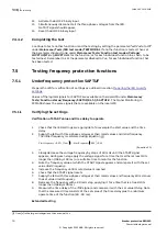
Use the formulas stated in
for the different calculation modes used. The set
mode
Mode can be found on the local HMI under Main menu/Settings/IED Settings/
Current/GUPPDUP(37,P<)/GUPPDUP:1/General.
Table 3:
Calculation modes
Set value:
Mode
Formula used for complex power calculation
L1, L2, L3
*
*
*
1
1
2
2
3
3
L
L
L
L
L
L
S
U
I
U
I
U
I
=
×
+
×
+
×
EQUATION1697 V1 EN-US
(Equation 4)
Arone
*
*
1 2
1
2 3
3
L L
L
L L
L
S
U
I
U
I
=
×
-
×
EQUATION1698 V1 EN-US
(Equation 5)
PosSeq
*
3
PosSeq
PosSeq
S
U
I
= ×
×
EQUATION1699 V1 EN-US
(Equation 6)
Table continues on next page
1MRK 505 293-UEN B
Section 7
Testing functionality
Breaker protection REQ650
63
Commissioning manual
© Copyright 2013 ABB. All rights reserved
Содержание REQ650 1.3 IEC
Страница 1: ...Relion 650 SERIES Breaker protection REQ650 Version 1 3 IEC Commissioning manual ...
Страница 2: ......
Страница 12: ...6 ...
Страница 20: ...14 ...
Страница 28: ...22 ...
Страница 40: ...34 ...
Страница 42: ...36 ...
Страница 116: ...110 ...
Страница 123: ...117 ...