


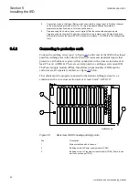


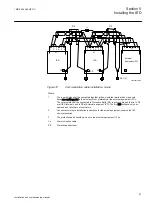


Use the main protective earth screw (1) for connection to the
stations earthing system. Earthing screws for PSM module (2) and
TRM module (3) must be fully tightened to secure protective earth
connection of these modules.
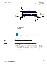
5.4.3
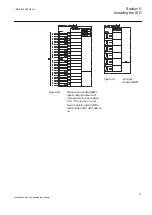
Connecting the power supply module
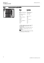
The wiring from the cubicle terminal block to the IED terminals (see figure
PSM connection diagram) must be made in accordance with the established
guidelines for this type of equipment. The wires from binary inputs and outputs and
the auxiliary supply must be routed separately from the current transformer cables
between the terminal blocks of the cubicle and the IED's connections. The
connections are made on connector X11. For location of connector X11, refer to
section
.
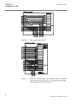
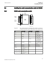
5.4.4
Connecting to CT and VT circuits
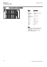
CTs and VTs are connected to the 24–pole connector of the Transformer input
module (TRM) on the rear side of the IED. Connection diagram for TRM is shown
in figure
.
Use a solid conductor with a cross section area between 2.5-6 mm
2
(AWG14-10)
or a stranded conductor with a cross section area between 2.5-4 mm
2
(AWG14-12).
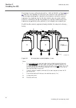
If the IED is equipped with a test-switch of type RTXP 24 COMBIFLEX wires
with 20 A sockets must be used to connect the CT and VT circuits.
Connectors on TRM (for location see section
) for current
and voltage transformer circuits are so called “feed-through IED blocks” and are
designed for conductors with cross sectional area up to 4 mm
2
(AWG 12). The
screws used to fasten the conductors should be tightened with a torque of 1Nm.
Connector terminals for CT and VT circuits, as well as terminals for binary input
and output signals, can be of either ringlug or compression connection type,
depending on ANSI/IEC standards, or customers choice.
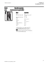
Table 8:
CT and VT circuit connectors
Connector type
Rated voltage and current
Maximum conductor area
Screw compression type
250 V AC, 20 A
4 mm
2
(AWG12)
2 x 2.5 mm
2
(2 x AWG14)
Terminal blocks suitable for
ring lug terminals
250 V AC, 20 A
4 mm
2
(AWG12)
1MRK 504 088-UEN C
Section 5
Installing the IED
59
Installation and commissioning manual
Содержание RELION RET670
Страница 1: ...Relion 670 series Transformer protection RET670 Installation and commissioning manual...
Страница 2: ......
Страница 16: ...10...
Страница 24: ...18...
Страница 26: ...20...
Страница 28: ...22...
Страница 82: ...76...
Страница 88: ...82...
Страница 94: ...88...
Страница 104: ...98...
Страница 110: ...104...
Страница 210: ...204...
Страница 230: ...224...
Страница 239: ...233...


