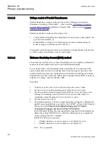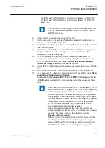
current measured at T2 and T3. The currents measured at T2
and T3 will ideally be about the same values.
If the voltage is close to the upper limit of the
UDeadband
,
the tap changer of T1 will try to decrease the controlled
voltage. In the opposite case, that is, the voltage is close to the
lower limit of
UDeadband
, the tap changer at T1 will not try
to decrease the controlled voltage.
The tap changer for T2 and T3 will not operate due to the fact
that the detected circulating current will be half of the current
detected at T1.
The setting of the parameter
Comp
then might need to be
increased a little.
At least one tap changer step difference between the different
transformers should be allowed in order to avoid the tap
changers to operate too often. If the allowed difference is for
example two steps, the tap changer shall be stepped up three
steps when setting the parameter
Comp
. This applies to all the
VCTR in the same group.
14. The setting of the parameter
Comp
at T2 and T3 will be carried out in the
same manner as at T1. According to the described procedure when the tap
changer of one transformer lies two steps above the others, it shall
automatically step down. When there are only two transformers in the group
either shall one step down or the other step up depending on the voltage level
at the VCTR.
15. Before placing the VCTR into service, confirm the correct settings of
USet
,
UDeadband
, the blocking settings for overcurrent, undervoltage and high
circulating currents, and the compensating parameters
Rline
and
Xline
.
Also confirm the settings in the Signal Matrix for binary RAISE and LOWER
outputs in conjunction with the basic CET configuration for Goose messages
between parallel transformer control functions.
16. Ensure that the automatic control mode is set for each transformer from the
IED and that
OperationPAR
is set to
CC
.
14.1.1.5
Master Follower (MF) method
Master follower method requires a Master to be nominated in a parallel group, that
is responsible for measuring secondary bus voltage, and executing commands to
raise and lower tap changers, that are repeated by Follower transformers in the group.
Procedure
1.
Confirm or set
USet
and
UDeadband
to the correct in the service values.
2.
Set the correct overcurrent blocking level (
IBlock
) in the service value.
3.
Set
Rline
and
Xline
to
Zero
.
4.
Confirm the setting of
MFMode
as
Follow Tap
or
Follow Cmd
. If this setting
is
Follow Tap
, all Follower transformers shall match the actual tap setting of
the Master, while
Follow Cmd
requires that Follower transformers follow the
Section 14
1MRK 504 088-UEN C
Primary injection testing
210
Installation and commissioning manual
Содержание RELION RET670
Страница 1: ...Relion 670 series Transformer protection RET670 Installation and commissioning manual...
Страница 2: ......
Страница 16: ...10...
Страница 24: ...18...
Страница 26: ...20...
Страница 28: ...22...
Страница 82: ...76...
Страница 88: ...82...
Страница 94: ...88...
Страница 104: ...98...
Страница 110: ...104...
Страница 210: ...204...
Страница 230: ...224...
Страница 239: ...233...


