205
Binary input module (BIM)
Chapter 13
Hardware modules
5
Binary input module (BIM)
5.1
Application
The binary input module has 16 optically isolated inputs and is available in two versions, one
standard and one with enhanced pulse counting inputs to be used with the pulse counter function.
5.2
Design
The binary input module, BIM, has 16 optically isolated binary inputs.
A signal discriminator detects and blocks oscillating signals. When blocked, a hysteresis func-
tion may be set to release the input at a chosen frequency, making it possible to use the input for
pulse counting. The blocking frequency may also be set.
5.3
Function block
Figure 80:
Binary input module
5.4
Input and output signals
Table 215: Input signals for binary input module BIM
Path in local HMI: ServiceReport/IO/Slotnn-BIMn/FuncOutputs
BINAME01
BINAME02
BINAME03
BINAME04
BINAME05
BINAME06
BINAME07
BINAME08
BINAME09
BINAME10
BINAME11
BINAME12
BINAME13
BINAME14
BINAME15
BINAME16
BI1
BI2
BI3
BI4
BI5
BI6
BI7
BI8
BI9
BI10
BI11
BI12
BI13
BI14
BI15
BI16
BIM
POSITION
ERROR
xx00000155.vsd
Signal
Description
POSITION
I/O module slot position
BINAME01-BINAME16
Input name string settings
Содержание REL 501-C1 2.5
Страница 1: ...Technical reference manual Line distance protection terminal REL 501 C1 2 5 ...
Страница 2: ......
Страница 26: ...14 Introduction to the technical reference manual Chapter 1 Introduction ...
Страница 42: ...30 Technical data Chapter 2 General ...
Страница 66: ...54 Blocking of signals during test BST Chapter 3 Common functions ...
Страница 142: ...130 Time delayed overvoltage protection TOV Chapter 6 Voltage ...
Страница 162: ...150 Autorecloser AR Chapter 9 Control ...
Страница 163: ...151 About this chapter Chapter 10 Logic Chapter 10 Logic About this chapter This chapter describes the logic functions ...
Страница 174: ...162 Event function EV Chapter 10 Logic ...
Страница 210: ...198 Serial communication Chapter 12 Data communication ...
Страница 226: ...214 Serial communication modules SCM Chapter 13 Hardware modules ...
Страница 227: ...215 Chapter 14 Diagrams Chapter 14 Diagrams This chapter contains the terminal diagrams for the terminal ...
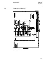
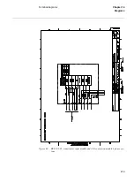
Страница 229: ...217 Terminal diagrams Chapter 14 Diagrams 1 2 Terminal diagram REL 501 C1 Figure 86 REL 501 C1 ...
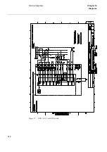
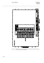
Страница 230: ...218 Terminal diagrams Chapter 14 Diagrams Figure 87 REL 501 C1 with DC switch ...
Страница 234: ...222 Terminal diagrams Chapter 14 Diagrams ...
Страница 237: ......


