


172
Supervision of AC input quantities (DA)
Chapter 11
Monitoring
4.4
Input and output signals
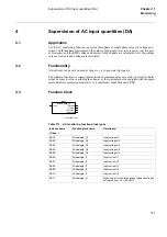
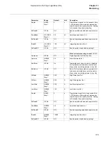
Table 172: Input signals for the AC monitoring (DAnn-) function block
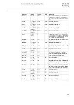
Use CAP configuration tool to se status of the output signals.
Table 173: Output signals for the AC monitoring (DAnn-) function block
4.5
Setting parameters
The PST, Parameter Setting Tool, must be used to set the parameters.
DA12-
DirAnalogIn_I
Mean value I of the three currents I1,I2 and I3
DA13-
DirAnalogIn_P
Three phase active power P measured by the first
three voltage and current inputs
DA14-
DirAnalogIn_Q
Three phase reactive power Q measured by the
first three voltage and current inputs
DA15-
DirAnalogIn_f
Mean value of frequency f as measured by the volt-
age inputs U1, U2 and U3
DA16-
DirAnalogIn_S
Three phase apparent power S measured by the
first three voltage and current inputs
Instance name
( DAnn- )
Function block name
Description
Signal
Description
BLOCK
Block updating of value for measured quantity
Signal
Description
HIALARM
High Alarm for measured quantity
HIWARN
High Warning for measured quantity
LOWWARN
Low Warning for measured quantity
LOWALARM
Low Alarm for measured quantity
Содержание REL 501-C1 2.5
Страница 1: ...Technical reference manual Line distance protection terminal REL 501 C1 2 5 ...
Страница 2: ......
Страница 26: ...14 Introduction to the technical reference manual Chapter 1 Introduction ...
Страница 42: ...30 Technical data Chapter 2 General ...
Страница 66: ...54 Blocking of signals during test BST Chapter 3 Common functions ...
Страница 142: ...130 Time delayed overvoltage protection TOV Chapter 6 Voltage ...
Страница 162: ...150 Autorecloser AR Chapter 9 Control ...
Страница 163: ...151 About this chapter Chapter 10 Logic Chapter 10 Logic About this chapter This chapter describes the logic functions ...
Страница 174: ...162 Event function EV Chapter 10 Logic ...
Страница 210: ...198 Serial communication Chapter 12 Data communication ...
Страница 226: ...214 Serial communication modules SCM Chapter 13 Hardware modules ...
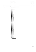
Страница 227: ...215 Chapter 14 Diagrams Chapter 14 Diagrams This chapter contains the terminal diagrams for the terminal ...
Страница 229: ...217 Terminal diagrams Chapter 14 Diagrams 1 2 Terminal diagram REL 501 C1 Figure 86 REL 501 C1 ...
Страница 230: ...218 Terminal diagrams Chapter 14 Diagrams Figure 87 REL 501 C1 with DC switch ...
Страница 234: ...222 Terminal diagrams Chapter 14 Diagrams ...
Страница 237: ......


