202
Transformer module (TRM)
Chapter 13
Hardware modules
3
Transformer module (TRM)
3.1
Design
A transformer input module can have up to 10 input transformers. The actual number depends
on the type of terminal. Terminals including only current measuring functions only have current
inputs. Fully equipped the transformer module consists of:
•
Five voltage transformers
•
Five current transformers
The inputs are mainly used for:
•
Phase currents
•
Residual current of the protected line
•
Residual current of the parallel circuit (if any) for compensation of the effect of
the zero sequence mutual impedance on the fault locator measurement or residual
current of the protected line but from a parallel core used for CT circuit supervi-
sion function or independent earth fault function.
•
Phase voltages
•
Open delta voltage for the protected line (for an optional directional earth-fault
protection)
•
Phase voltage for an optional synchronism and energizing check.
3.2
Technical data
Table 211: TRM - Energizing quantities, rated values and limits
Quantity
Rated value
Nominal range
Current
I
r
= 1 or 5 A
(0.2-30)
×
I
r
Operative range
(0.004-100) x I
r
Permissive overload
4
×
I
r
cont.
100
×
I
r
for 1 s
*)
Burden
< 0.25 VA at I
r
= 1 or 5 A
Ac voltage for the terminal
U
r
= 110 V **)
U
r
= 220 V **)
100/110/115/120 V
200/220/230/240 V
Operative range
(0.001-1.5) x U
r
Permissive overload
2.3
×
U
r
phase-earth, cont.
3.0 x U
r
phase-earth, for 1 s
Burden
< 0.2 VA at U
r
Frequency
f
r
= 50/60 Hz
+/-10%
*)
max. 350 A for 1 s when COMBITEST test switch is included.
**) The rated voltage of each individual voltage input U1 to U5 is U
r
/√
3
Содержание REL 501-C1 2.5
Страница 1: ...Technical reference manual Line distance protection terminal REL 501 C1 2 5 ...
Страница 2: ......
Страница 26: ...14 Introduction to the technical reference manual Chapter 1 Introduction ...
Страница 42: ...30 Technical data Chapter 2 General ...
Страница 66: ...54 Blocking of signals during test BST Chapter 3 Common functions ...
Страница 142: ...130 Time delayed overvoltage protection TOV Chapter 6 Voltage ...
Страница 162: ...150 Autorecloser AR Chapter 9 Control ...
Страница 163: ...151 About this chapter Chapter 10 Logic Chapter 10 Logic About this chapter This chapter describes the logic functions ...
Страница 174: ...162 Event function EV Chapter 10 Logic ...
Страница 210: ...198 Serial communication Chapter 12 Data communication ...
Страница 226: ...214 Serial communication modules SCM Chapter 13 Hardware modules ...
Страница 227: ...215 Chapter 14 Diagrams Chapter 14 Diagrams This chapter contains the terminal diagrams for the terminal ...
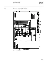
Страница 229: ...217 Terminal diagrams Chapter 14 Diagrams 1 2 Terminal diagram REL 501 C1 Figure 86 REL 501 C1 ...
Страница 230: ...218 Terminal diagrams Chapter 14 Diagrams Figure 87 REL 501 C1 with DC switch ...
Страница 234: ...222 Terminal diagrams Chapter 14 Diagrams ...
Страница 237: ......


