background image

17

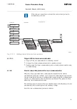
1. The backlight is turned on after the relay has performed the internal power-up

tests and entered into the protection mode.

2. The display is tested by inverting it for approximately three seconds, see

Fig. 4.1.3.1.-1.

3. The display is returned to the idle mode and the backlight is turned off if no

operation target message is displayed. However, if the non-volatile function is
active, a message shown on the display before the auxiliary voltage was
disconnected reappears on the display.

A040216

Fig. 4.1.3.1.-1

Display test at power up, display inverted
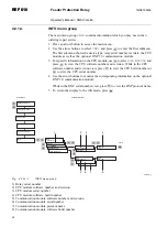
4.1.3.2.

Display modes

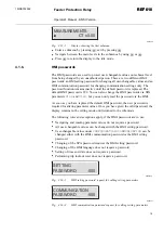
When the display is in the idle mode, the name of the feeder is displayed, which by
default is

- ABB -

. To change the name of the feeder, use SPA parameter

M20

.

-              ABB              -

A040217

Fig. 4.1.3.2.-1

Display in the idle mode

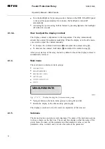
When the display is in the view mode, you can only view the settings.

SETTINGS

*GRP1                 : 3.50

A040218

Fig. 4.1.3.2.-2

Display in the view mode

When the display is in the setting mode, you can also edit the settings.

SETTINGS

*GRP1               : 3.5 1

A040219

Fig. 4.1.3.2.-3

Display in the setting mode

4.1.3.3.

Display backlight

Normally the backlight of the display is off.

Feeder Protection Relay

Operator's Manual - ANSI Version

REF 610

REF 610

1MRS755539

Содержание REF 610

Страница 1: ...Feeder Protection Relay REF 610 REF 610 Operator s Manual ANSI Version...

Страница 2: ......

Страница 3: ...18 4 1 5 Submenu 18 4 1 6 HMI passwords 19 4 1 7 SPA password 20 4 1 8 How to select language 21 4 1 9 How to set the real time clock 22 4 1 10 How to reset the trip lockout function 23 4 1 11 How to...

Страница 4: ...duct 46 4 4 2 Detaching and installing the plug in unit 47 4 4 3 Inserting and changing the battery 49 5 Commissioning and maintenance 51 5 1 Commissioning instructions 51 5 2 Maintenance instructions...

Страница 5: ...ereof must not be reproduced or copied without written permission from ABB Oy and the contents thereof must not be imparted to a third party nor used for any unauthorized purpose The software or hardw...

Страница 6: ...6...

Страница 7: ...information or warning related to the concept discussed in the text It might indicate the presence of a hazard which could result in corruption of software or damage to equipment or property The info...

Страница 8: ...ush button icons for example To navigate between the options use and HMI menu paths are presented as follows Use the arrow buttons to select CONFIGURATION COMMUNICATION SPA SETTINGS PASSWORD SPA Param...

Страница 9: ...sion IED Revision Date History A A 05 10 2004 Document created Modified for ANSI compliance from the IEC version A B C 31 01 2007 Content updated Feeder Protection Relay Operator s Manual ANSI Version...

Страница 10: ...10...

Страница 11: ...to be carefully grounded When the plug in unit has been detached from the case do not touch the inside of the case The relay case internals may contain high voltage potential and touching these may ca...

Страница 12: ...12...

Страница 13: ...t element Three phase non directional overcurrent protection instantaneous element Non directional ground fault protection with definite time or IDMT characteristic low set element Non directional gro...

Страница 14: ...numeric LCD and navigation buttons Eight programmable LEDs Multi language support User selectable password protection for the HMI Display of primary current values Demand values All settings can be mo...

Страница 15: ...ting in the menu structure and in adjusting setting values Optically isolated serial communication port with a target LED 1 2 3 4 5 6 A040214_2 Fig 4 1 1 1 Front view of the relay 1 LCD 2 HMI push but...

Страница 16: ...d in the main menu or a submenu Entering a submenu from the main menu or a higher submenu Leaving a submenu for the main menu or a higher submenu Increasing a value in the setting mode Decreasing a va...

Страница 17: ...3 1 1 Display test at power up display inverted 4 1 3 2 Display modes When the display is in the idle mode the name of the feeder is displayed which by default is ABB To change the name of the feeder...

Страница 18: ...he relay the factory default value of the display contrast is automatically restored 4 1 4 Main menu The main menu contains six main groups OPERATION MEASUREMENTS RECORDED DATA SETTINGS CONFIGURATION...

Страница 19: ...password is required for altering parameter values Once you have given the valid password the display remains in the setting mode until returned to the idle mode The following rules and exceptions ap...

Страница 20: ...o the idle mode The same procedure applies also when changing the HMI communication password Main Menu Group Menu Parameter Menu SETTINGS CONFIGURATION MEASUREMENTS RECORDED DATA HMI PASSWORDS TIME TR...

Страница 21: ...S CONFIGURATION MEASUREMENTS RECORDED DATA COUNTER xxx UNIT ADDRESS xxx MODBUS SETTINGS SPA SETTINGS REAR PROTOCOL CONFIGURATION FUNCTION TEST DI COMMUNICATION LANGUAGE REAR CONNECTION CONFIGURATION I...

Страница 22: ...STORE COUNTER A070063 Fig 4 1 8 1 Selecting language The list of languages in the language selection menu differs depending on the HMI language set number in the order number 4 1 9 How to set the rea...

Страница 23: ...I COMMUNICATION LANGUAGE FREQUENCY CONFIGURATION CONFIGURATION MEMORY SETTINGS HMI PASSWORDS TIME INFO YY MM DD 00 23 hh mm ss 00 59 OPERATION STORE COUNTER A040238_2 Fig 4 1 9 1 Setting the real time...

Страница 24: ...not allowed If the optional rear communication module is installed and enabled the default setting is the rear connection Switch between front and rear connection as follows 1 Press an arrow button to...

Страница 25: ...rear communication is currently selected Lit target the front communication port is currently selected Flashing target the front communication port is currently selected and the relay is communicating...

Страница 26: ...ADDRESS xxx MODBUS SETTINGS SPA SETTINGS REAR PROTOCOL REAR CONNECTION CONFIGURATION IEC103 SETTINGS Confirm Cancel TRIP CIRCUIT SUP REAR COM MODULE INFO OPERATION COM MODULE STORE COUNTER A040244_2 F...

Страница 27: ...cess the main menu 2 The cursor is at the first menu item MEASUREMENTS Press to see the measured value on phase Ia 3 Use and to monitor the measured values on phases Ia Ib and Ic and the measured valu...

Страница 28: ...multaneously to view the primary line currents on phases Ia Ib and Ic and the ground fault current In 2 Press to return the display to the idle mode The display has to be in the idle mode to be able t...

Страница 29: ...TA RECORDED DATA RECORDED DATA INFO 1 la CT x xx 1 lb CT x xx 1 lc CT x xx 1 50P 1 DUR x xx 1 51P DUR x xx 1 ln CT x x 1 51N DUR x xx 1 HH MM SS SSS 1 YY MM DD 51P TRIP x PICKUP 51P PU x 50P 2 PU x 51...

Страница 30: ...e corresponding information on the optional DNP 3 0 communication module While in the DNP serial number view press to view the DNP protocol name 5 To return the display to the idle mode press 5 6 7 8...

Страница 31: ...PROTECT ELEMENTS 59P 1 VTx0 00 Submenu Parameter Menu SETTINGS GRP 2 x xx GRP 1 x xx SETTINGS Confirm Cancel 51P CT 0 00 A070069 Fig 4 2 2 2 1 Setting parameters in setting group 1 and setting group 2...

Страница 32: ...d 999 is still valid no password is required 6 The first digit of the setting value of the parameter to be edited starts to flash Use and to move the cursor and and to increase or decrease the number...

Страница 33: ...1 CT x 0 00 51P CT x 0 00 51P TDLY 51P RSET s x xx 50P 1 TDLY x xx 50P 2 CT x 0 00 50P 2 TDLY x xx INFO OPERATION 51N CT x x 51N TDLY s x xx 51N Mode x 51N TD IEC x xx 51N TD ANSI x x 51N RSET s x xx...

Страница 34: ...and press 3 Use or to select the wanted switchgroup for example SGF2 for display settings and press 4 Use or to select setting group 1 or 2 GRP1 or GRP2 The active setting group is indicated by an ast...

Страница 35: ...xxxxxxxx SGL7 xxxxxxxx SGL1 xxxxxxxx SGL8 xxxxxxxx SGF5 xxx SGF2 xxx SGF3 xxx SGF4 x SGF1 xxx SGB5 xxxx SGB2 xxxx SGB3 xxxx SGB4 xxxx SGB1 xxxx Edit Confirm Cancel INFO OPERATION AUTO RECLOSE SGR6 xx...

Страница 36: ...h Set the enumerator or the digit character by using and Activate the next digit character to be set by pressing or When setting an enumerator however the left and right arrows have no function 6 To s...

Страница 37: ...C ORDER LOW HIGH EVEN PARITY ODD PARITY NO PARITY IEC103 SETTINGS BAUD RATE 9 6 PASSWORD SPA xxx CONFIGURATION DISABLED ENABLED CONFIGURATION STAR LOOP CONFIGURATION LIGHT OFF CONFIGURATION REAR COM M...

Страница 38: ...dge and reset targets output contacts and memorized values To clear the LEDs and the display press The LEDs and the display are cleared only if the fault has disappeared To unlatch the output contacts...

Страница 39: ...otection element is blocked the yellow target LED starts to flash The yellow target LED is also lit to indicate an alarm from a protection element 4 3 1 1 Green target LED A040264 Fig 4 3 1 1 1 Green...

Страница 40: ...with the digital input signal The yellow target LED continues flashing for as long as a protection element remains blocked The blocking target disappears with the digital input signal or when the pro...

Страница 41: ...fer to the Technical Reference Manual The LEDs are non latching by default but you can also set them to operate as latching via switchgroup SGF5 For instructions on setting the switchgroups refer to S...

Страница 42: ...LARM will appear on the display to indicate that the CB has been left in the open position and that no more auto reclosures are being generated If a pickup or trip target for the element that initiate...

Страница 43: ...etting value has expired After this a new trip target message can replace the old one A hidden trip target message can be brought forward by pressing 4 3 2 2 Disturbance recorder target When the displ...

Страница 44: ...PO2 SO1 or SO2 10 11 12 Error in the feedback enable signal or output relay PO1 PO2 SO1 or SO2 13 Error in optional output relay SO3 14 Error in optional output relay SO4 15 Error in optional output r...

Страница 45: ...ssage indicating the fault type replaces the name of the feeder on the display in the idle mode Some of these faults can be corrected by a relay operator at site After the fault has disappeared or bee...

Страница 46: ...has been disabled In case only this warning is active it is displayed in text format Comm card faulty DNP 3 0 configuration error 16 DNP 3 0 configuration error DNP 3 0 parameters should be formatted...

Страница 47: ...he handle are released and the unit is pushed about 6 mm out of the case This separates the connectors 2 Pull the unit out of the case The relay features an automatic short circuit mechanism in the cu...

Страница 48: ...mber of the substitute plug in unit except for those indicating a spare part should match the ones of the case Otherwise it may result in loss of significant functionality in the application The relay...

Страница 49: ...with for example a flat ended screwdriver Be careful not to drop the battery inside the plug in unit 2 Insert a new battery under the battery holder and ensure that you install the battery with the co...

Страница 50: ...A B C A040282_2 Fig 4 4 3 1 Inserting and changing the battery A Battery holder B Note Polarity C Battery 50 REF 610 REF 610 Feeder Protection Relay Operator s Manual ANSI Version 1MRS755539...

Страница 51: ...ntive maintenance to be performed every five years This periodically performed preventive maintenance is to be carried out to secure correct and safe operation of the relay When performing preventive...

Страница 52: ...Testing of signal routing to output contacts refer to Section 5 4 Function test 4 Testing of digital input signals availability refer to Section 5 5 Digital input test 5 Testing of the optional arc d...

Страница 53: ...in section Arc detection test 5 2 2 Preventive parts replacement When being used for real time clock and recorded data functions the battery should be changed every five years Refer to Section 4 4 3...

Страница 54: ...e main menu and press The cursor is at the first menu item FUNCTION TEST DI Press again to enter the test menu 3 The cursor is at the first parameter FUNC TEST Press to enter the test mode and give th...

Страница 55: ...ss The cursor is at the first menu item FUNCTION TEST DI Press again to enter the test menu 3 Use or to select DI STATUS and press to see the status of DI1 4 Use and to monitor the state of the other...

Страница 56: ...ely upon detection of light with a switch in SGF4 5 7 Testing protection functions The short circuit and ground fault protection functions in the relay can be tested with the setting values used durin...

Страница 57: ...set operate time of element 50P 1 5 7 2 Testing of the ground fault protection When calculating the current to be injected into the ground fault current energizing input the calculation should be done...

Страница 58: ...58...

Страница 59: ...This helps to prevent dangerous situations from arising in case a non suitable plug in unit is fitted into a relay case Forcing a non suitable plug in unit into a case breaks the relay and may cause...

Страница 60: ...60...

Страница 61: ...rhaul of electronics are to be taken by the manufacturer Contact the manufacturer or the nearest representative for further information on checking service and re calibration of the relay When contact...

Страница 62: ...62...

Страница 63: ...63 8 Ordering information For ordering information refer to the Technical Reference Manual Feeder Protection Relay Operator s Manual ANSI Version REF 610 REF 610 1MRS755539...

Страница 64: ...64...

Страница 65: ...characteristic IEC International Electrotechnical Commission IED Intelligent electronic device IRF Internal relay fault LCD Liquid crystal display LED Light emitting diode PC Personal computer PO Pow...

Страница 66: ......

Страница 67: ......

Страница 68: ...ABB Oy Distribution Automation P O Box 699 FI 65101 Vaasa FINLAND 358 10 2211 358 10 224 1080 www abb com substationautomation 1MRS755539 EN 1 2007...

Отзывы: