


15
4.
Operation
4.1.
HMI features
4.1.1.
Front panel
The front panel of the relay contains:
*
Alphanumeric 2 × 16 characters
’
LCD with backlight and automatic contrast
control
*
Threetarget LEDs (green, yellow, red) with fixed functionality
*
Eight programmable target LEDs (red)
*
HMI push-button section with four arrow buttons and buttons for clear/cancel
and enter, used in navigating in the menu structure and in adjusting setting values
*
Optically isolated serial communication port with a target LED.
1
2
3
4
5
6
A040214_2
Fig. 4.1.1.-1
Front view of the relay
1) LCD
2) HMI push-button section
3) Programmable target LEDs (red)
4) Target LEDs:
*
Left: Ready (green)
*
Center: Pickup/Alarm (yellow)
*
Right: Trip (red)
5) Target LED for front communication
6) Front communication port (infrared)
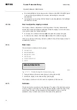
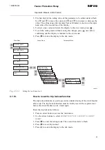
4.1.2.
How to use the push buttons
The HMI contains push buttons for navigating in the menu.
Feeder Protection Relay
Operator's Manual - ANSI Version
REF 610
REF 610
1MRS755539