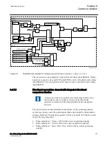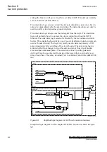
•
parallel connection of current instrument transformers in all three phases
(Holm-Green connection).
•
one single core balance current instrument transformer (cable CT).
•
one single current instrument transformer located between power system
star point and earth (current transformer located in the star point of a star
connected transformer winding).
•
one single current instrument transformer located between two parts of a
protected object (current transformer located between two star points of
double star shunt capacitor bank).
2. calculated from three-phase current input within the IED (when the fourth
analog input of the pre-processing block, connected to EF4PTOC function
Analog Input I3P, is not connected to a dedicated CT input of the IED in
PCM600). In such a case, the pre-processing block will calculate 3I
0
from the
first three inputs into the pre-processing block by using the following formula
(will take 3I
0
from SMAI AI3P and will be connected to I3PDIR and I3P
inputs.
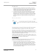
If the zero sequence current is selected,
Iop 3I
IL1 IL2 IL3
0
=
=
+
+
EQUATION1874 V2 EN-US
(Equation 23)
where:
IL1, IL2 and IL3
are fundamental frequency phasors of three individual phase currents.
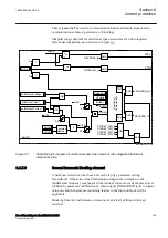
The residual current is pre-processed by a discrete Fourier filter. Thus the phasor of
the fundamental frequency component of the residual current is derived. The
phasor magnitude is used within the EF4PTOC protection to compare it with the
set operation current value of the four steps (
IN1>
,
IN2>
,
IN3>
or
IN4>
).
If the residual current is larger than the set operation current and the step is used in
non-directional mode a signal from the comparator for this step is set to true. This
signal will, without delay, activate the output signal STINx (x=step 1-4) for this
step and a common START signal.
8.4.7.2
Internal polarizing
M13941-82 v11
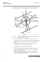
A polarizing quantity is used within the protection in order to determine the
direction to the earth fault (forward/reverse).
The function can be set to use voltage polarizing, current polarizing or dual
polarizing.
Voltage polarizing
When voltage polarizing is selected, the protection will use the residual voltage
-3U
0
as the polarizing quantity U3P.
Section 8
1MRK 505 394-UEN A
Current protection
192
Line differential protection RED650 2.2 IEC
Technical manual
Содержание RED650
Страница 1: ...RELION 650 SERIES Line differential protection RED650 Version 2 2 Technical manual...
Страница 2: ......
Страница 36: ...30...
Страница 46: ...40...
Страница 232: ...226...
Страница 272: ...266...
Страница 288: ...282...
Страница 306: ...300...
Страница 406: ...400...
Страница 436: ...430...
Страница 502: ...496...
Страница 614: ...608...
Страница 628: ...622...
Страница 644: ...638...
Страница 760: ...754...
Страница 778: ...772...
Страница 814: ...808...
Страница 870: ...864...
Страница 874: ...868...
Страница 924: ...918...
Страница 925: ...919...


