background image

DEFAULT DATA MAP


DATA MAPPING


50


1TGC908004


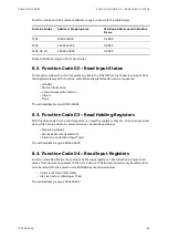
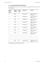
Monitoring with Function Code 02


Monitoring of the life and status bits of each M10x via the Digital Gateway is detailed in the 
following tables.


Modbus 


Function 
Code


Modbus 
Register


Device 
Number


Description


Remarks


2


10001


1


Life-Bit M10x 1 


M10x 1 is available 
(comm. ok)


2


10002


2


Life-Bit M10x 2


M10x 2 is available 
(comm. ok)


2


10003


3


Life-Bit M10x 3 


M10x 3 is available 
(comm. ok)


2


10004


4


Life-Bit M10x

 4 


M10x 4 is available 
(comm. ok)


2


10005


5


Life-Bit M10x 5 


M10x 5 is available 
(comm. ok)


2


10006


6


Life-Bit M10x 6 


M10x 6 is available 
(comm. ok)


2


10007


7


Life-Bit M10x 7 


M10x 7 is available 
(comm. ok)


2


10008


8


Life-Bit M10x 8 


M10x 8 is available 
(comm. ok)


:


:


:


:


:


:


:


:


:


:


:


:


:


:


:


2


10128


128


Life-Bit M10x 128 


M10x 128 is available 
(comm. ok)


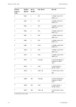
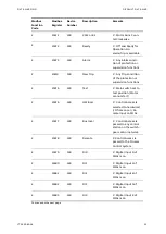
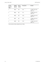
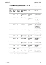
Table 20 Default Modbus Map Life Bit of M10x


Содержание LVS Digital

Страница 1: ... DISTRIBUTION SOLUTIONS LVS Digital with M10x Motor Controller Interface Manual Modbus ...

Страница 2: ...otect these products the network its system and interfaces against security breaches unauthorized access interference intrusion leakage and or theft of data or information ABB performs functionality testing on the products and updates that we release However system product owners are ultimately responsible for ensuring that any product updates or other major system updates to include but not limit...

Страница 3: ...hronization 22 5 3 1 Option 1 22 5 3 2 Option 2 23 5 4 DCS Fieldbus 24 5 4 1 Modbus RTU Topology 24 5 4 2 Modbus TCP Topology 27 6 Redundancy 28 6 1 Redundant Architecture 28 6 2 Redundancy Configuration 30 6 2 1 RedundantDigital Gateway connection 30 6 2 2 M10x Redundant Configuration 31 6 2 3 Digital Gateway Redundant Configuration 31 6 3 Handling of redundancy faults 33 6 4 MView Web Interface ...

Страница 4: ...Function Code 16 Preset Multiple Register 47 8 9 Restrictions 47 8 9 1 General 47 8 9 2 Modbus RTU 47 8 10 Exception Code Handling 48 9 Data Mapping 49 9 1 User Data Map 49 9 2 Default Data Map 49 9 2 1 Monitoring Inputs from M10x 49 9 2 2 Monitoring with Function Code 02 50 9 2 3 Monitoring with Function Code 03 and 04 55 9 2 4 Extended Status Description 56 9 2 5 Control Commands 59 9 2 6 Switch...

Страница 5: ... DCS 24 Figure 18 Digital Gateway RS422 connection via Serial 2 to DCS 25 Figure 19 Digital Gateway RS485 connection via Serial 2 to DCS 26 Figure 20 Example for RS485 bus termination and biasing 26 Figure 21 Digital Gateway Modbus TCP connection with Crossover cable 27 Figure 22 Digital Gateway Modbus TCP connection with standard CAT5 cable 27 Figure 23 Redundant configuration and possible failur...

Страница 6: ......

Страница 7: ...e 17 Byte representation for function code 03 and 04 46 Table 18 Byte representation for Float 46 Table 19 Byte representation for Float Big Endian 46 Table 20 Default Modbus Map Life Bit of M10x 50 Table 21 Default Modbus Map Bit Status of M10x 54 Table 22 Default Modbus Map Measured Values of M10x 55 Table 23 Default Modbus Map Extended Status for M10x 56 Table 24 Extended Status Byte 1 56 Table...

Страница 8: ......

Страница 9: ...r other important information It also includes Tip icons to point out useful hints to the reader The corresponding symbols should be interpreted as follows The electrical warning icon indicates the presence of a hazard that could result in electrical shock The warning icon indicates the presence of a hazard that could result in personal injury The caution icon indicates important information or wa...

Страница 10: ...net Ethernet is a local area network LAN technology The Ethernet standard specifies the physical me dium access control rules and the message frames Event An event is a status transition from one state to another It can be defined as alarm if the state is defined as abnormal or as warning as a pre alarm state FD Field Device Term for devices connected to the Fieldbus e g motor control units or cir...

Страница 11: ...U Fieldbus communication protocol MODBUS TCP IP Fieldbus communication protocol based on Ether net hardware Motor Starter Consists of motor controller and electrical com ponents to control and protect a motor part of Motor Control Center NeoGear Modular Low Voltage Switchgear family from ABB NLS Native Language Sup port Providing the ability to change the language of software tools in order to sup...

Страница 12: ...ion in Con trol Network through Ethernet Switchgear Bus Net work Term used to describe the internal switchgear communication network between Digital Gate way and M10X TCP IP Transmission Control Protocol Internet Protocol TCP IP is a high level connection oriented relia ble full duplex communication protocol devel oped for integration of the heterogeneous sys tems Trip A consequence of an alarm ac...

Страница 13: ... Implementation 1TNC911204 M10x M Control System Integration Guide 1TGC908001 ABB Ability Condition Monitoring for electrical systems CMES User Manual 1TNA810039 Manufacturing Instruction Installation of MService and MNS Digital Gateway in MNS 1TGC908028 LVS Digital Interface Manual Web Server ...

Страница 14: ...as to the CMES Edge which provides condition monitoring features and functions as well as edge con nectivity to ABB Ability cloud based solutions Figure 1 Digital Gateway One Digital Gateway can communicate internally to up to 128 M10x field devices by Modbus RTU or Modbus TCP If more than 128 M10x field devices are installed then additional Digi tal Gateway must be configured Figure 2 General LVS...

Страница 15: ...INTRODUCTION RELATED DOCUMENTATION 1TGC908004 7 Figure 3 General LVS Digital System Configuration with M10x TCP ...

Страница 16: ...S422 RS232 Ethernet TCP IP IEEE 802 3 Digital Gateway ID 1TGE120021R0810 1TGE120021R0610 Picture Table 1 Digital Gateway Modbus Hardware M10x variant Communication protocol to Digital Gateway M10x M Modbus RTU RS485 As one segment of Modbus RTU is only able to support 32 devices Digital Gateway for M10x M is supplied with an additional Serial inter face card which provides four Modbus RTU port to ...

Страница 17: ... Consumption Typical 800mA maximum 1000mA MECHANICAL DATA Weight 2 5 kg Dimensions H x W x D 140 x 160 x 246 mm ENVIRONMENTAL DATA Storage Temperature 20o C to 70o C Operating Temperature 0o C to 55o C Degree of Protection IP51 MTBF Mean Time Between Failures 46 years 40o C Table 3 Digital Gateway Technical Data ...

Страница 18: ...odes The MODBUS communication protocol is implemented within the Digital Gateway to enable LVS Digital to provide interface possibilities to process control systems or any other external systems that supports MODBUS RTU TCP protocol handling The MODBUS configuration can be used in point to point configuration or in multi drop mode In Master Slave MODBUS architecture the Digital Gateway is always u...

Страница 19: ...se of the Digital Gateway the trans mission mode is also limited to RTU or TCP Other characteristics are user selectable These include a choice of transmission medium baud rate and character parity number of stop bits These parameters cannot be changed while the communication interface is active The OSI layers 1 2 and 7 are implemented in the Digital Gateway Layer 1 2 In these layers the physical ...

Страница 20: ...y deals with either type of error as specified in MODBUS specification The most frequent cause of communication error is noise unwanted electrical signals in a communication channel These signals occur because of electrical interference from machinery damage to the communication channel impulse noise spikes etc Character framing a parity check and a redundancy check detect these errors When the er...

Страница 21: ... view M10x serial 4 port connector for Modbus RTU field device connectivity Interface card only availa ble for 1TGE120021R0810 Redundancy connector Serial 1 DCS SCADA Modbus RTU connector Serial 2 LAN3 port for Modbus TCP field device connectivity LAN1 port for DCS SCADA Modbus TCP connectivity ...

Страница 22: ...ld device connectivity via Modbus TCP LAN 3 LED left green Link LAN 3 active LAN 3 LED right yellow Communication Ethernet LAN 3 USB 1 2 Not used Serial 1 Redundancy Interface male plug Serial 2 Modbus RTU Interface female plug LED INDICATIONS LED 1 Digital Gateway Run indication CF card application loaded and running LED 2 Digital Gateway Fault LED 3 Application dependent see section LED indicati...

Страница 23: ...gital Gateway requires 24V DC supply voltage The connection is on the left side of the device with terminal plugs Terminal 1 connects to 24V DC Terminal 2 connects to 0V DC Figure 6 Power Supply Connector 1 Power Supply 24VDC 2 Power Supply 0VDC 1 2 ...

Страница 24: ...nside the switchgear utilizing a Digital Gateway mounting kit which is housed in an 8E withdrawable module compartment of the MNS cubi cle mounting kit part ID 1TNA704001R0003 or respective compartment in NeoGear switch gear The Digital Gateway mounting kit for MNS is capable to support mounting of up to three Dig ital Gateway Figure 7 Digital Gateway Mounting Kit for MNS ...

Страница 25: ...on of the Digi tal Gateway in the switchgear environment The CF card slot is located on the Digital Gateway front side To remove or insert the CF card the power supply connector must be removed and the metal cover must be lifted This en sures that CF card can only be removed inserted while power supply is off CF card shall be inserted with the correct side up and with care as the card is mechanica...

Страница 26: ...esistors are required as terminators for both end of each communication link The Digi tal Gateway has an inbuilt terminating resistor on its serial port which acts as a first point while for the last point one 120 Ohm resistor needs to be installed Figure 10 Hardware connection between Digital Gateway and M10x M The settings required in M10x to establish the communication between M10x and Digital ...

Страница 27: ...ntroller The communication between Digital Gateway and M10x TCP is established via Modbus TCP protocol M10x TCP supports standard star but also ring topology communication MRP protocol in cases increased communication availability is required Figure 12 Hardware connection between Digital Gateway and M10x TCP Parameterization of communication setting in M10x can be done either via the MD panel on t...

Страница 28: ...orized access e g through Router and Firewall This is a project specific configuration Contact always the local network administrator and review the project specific requirements If managed switches or routers are used in the Ethernet network it has to be taken care that sent ARP messages can pass through Background After reboot Digital Gateway will send an ARP Address Resolution Protocol mes sage...

Страница 29: ...able Figure 14 Network connection of Digital Gateway and CMES Edge It is recommended that a managed network switch is used to connect the Digital Gateway to the PCS or PLC The switch may be delivered together with the switch board depending on project scope definition To ensure proper system performance following design rules shall be obeyed Not more than 2 MView optional shall be connect to one D...

Страница 30: ...component is installed which can provide the time signal as NTP Server Such an NTP Server can be a computer or network server as well as Ethernet switches As an option this NTP Server can be equipped with a GPS Receiver to provide accurate time for the location In case of Option 1 Time Server hardware is not part of MNS and has to be supplied separately If the Time Server is out of service the Dig...

Страница 31: ...y are configured as NTP Client Time Sync mode NTP and their internal clock is synchronized by the NTP Server Digital Gateway In case of a power down the Digital Gateway buffers the system time RTC for about 3 hours Afterwards its internal clock is reset to 2009 01 01 This time synchronization method is less accurate than Option 1 since one Digital Gateway internal clock is used as time reference a...

Страница 32: ...on speed and repeater type in use Cable length can be extended using fiber optic modems which in addition also galvanically isolate the communication prevent shield currents and provides best option for EMC immunity The serial port interface of the Digital Gateway is not galvanically isolated To achieve this it is recommended to use 3rd party product if required 5 4 1 1 RS232 Allows only a simple ...

Страница 33: ...1TGC908004 25 5 4 1 2 RS422 Allows simple point to point topology between Master and Slave The maximum distance ac cording to the standard is 1000 meters depending on communication speed Figure 18 Digital Gateway RS422 connection via Serial 2 to DCS ...

Страница 34: ... depending on communication speed Figure 19 Digital Gateway RS485 connection via Serial 2 to DCS 5 4 1 4 Termination The RS485 bus must be terminated at both ends The Digital Gateway does not provide an in built MODBUS RTU termination for RS485 com munication therefore correct measures must be taken to connect termination to both ends of the segment Figure 20 Example for RS485 bus termination and ...

Страница 35: ... connector on the Digital Gateway For a direct connection a CAT 5 or higher cross over cable is to be used For a net work with multiple slaves via a network switch the standard CAT 5 patch cables are used Figure 21 Digital Gateway Modbus TCP connection with Crossover cable Figure 22 Digital Gateway Modbus TCP connection with standard CAT5 cable ...

Страница 36: ...teway The Backup Digital Gateway reads the information only and is inhibited from sending switch ing commands The Primary and Backup Digital Gateway is synchronized using a redundant link cable A redundant system does can cover single system failures Following theoretical failure situa tions are covered by a redundant systemconfiguration On an active communication link Failure in a PLC Fieldbus ma...

Страница 37: ...m one of the 2 cases detailed above an integrated system mecha nism ensures a bump less changeover from the Primary Digital Gateway to the Backup Digi tal Gateway All process data alarms and events and the system status information are then available from the Backup Digital Gateway which will become the Primary Digital Gateway af ter the switch over ...

Страница 38: ...teway see example Figure 23 24 Redundant Digital Gateway connection Both Digital Gateway must be connected via a RS232 Null Modem cable port Serial 1 on both Digital Gateway to enable data synchronization and ensure correct operation Figure 25 Serial 1 to serial 1 redundant link connections with ferrite core The length of this cable should not exceed 10 meters Redun dant Link Cables 2m 1TGE120109R...

Страница 39: ...te tool The parameters must then be downloaded to both the Primary and Backup Digital Gateway to become effective In a project with multiple Digital Gateway most of the Digital Gateway parameter are identi cal To ease the parameterization such parameters could be copied among the Digital Gate way Assign to Digital Gateway As Network address settings are different between the Digital Gateways if co...

Страница 40: ... Digi tal Gateway is different e g Primary 192 168 200 100 Backup 192 168 200 101 The same subnet mask is used because both Ethernet ports are connected to the same Ethernet network for MView and MNavigate communication Digital Gateway LAN3 is not used for M10x applications 2 Set the slave address for the selected Fieldbus Field network interface Figure 27 MNavigate Fieldbus Slave address Paramete...

Страница 41: ...e over Redundancy error indi cated Power loss of backup Digital Gateway No change over Redun dancy error indicated Problems in redundancy setup No change over possible Redundancy error indi cated Switchgear Bus at Primary Digital Gateway disconnected Redundancy change over Table 10 Primary and Backup IP address setting A change over from Primary to Backup Digital Gateway will only be performed if ...

Страница 42: ...way before without user interaction While redirecting the MView shows the following window Prior to the re direction the background in MView changes to yellow to indicate that current Web Interface is connected to the Backup Digital Gateway Once it has re directed to the new Primary Digital Gateway the background returns to its usual color Below screenshots are showing such a change over scenario ...

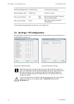
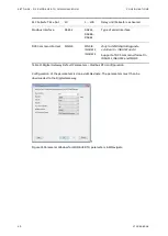
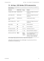
Страница 43: ...al Gateway Fieldbus communication related pa rameter e g comm speed or slave address can be change during runtime of Digital Gateway Parameter Default Value Range Remarks IP Address LAN 2 LAN2 192 168 200 100 Settings according to network administrator Subnet Mask LAN2 255 255 255 0 Settings according to network administrator Broadcast Address LAN2 192 168 200 255 Calculated automatically Default ...

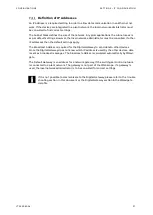
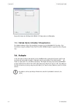
Страница 44: ...ion settings and parameterization for the Digital Gateway are configured with the MNavigate software tool Figure 30 IP Address Settings Figure 31 Time Sync Settings Digital Gateway does not support DHCP service to get automatic network ad dress If the default IP Address and Subnet Mask must be manually adjusted the parameter above has to be modified and copied to the Digital Gateway Any change in ...

Страница 45: ...tings apply The Broadcast Address is required for the Digital Gateway to send data to other devices Since the Digital Gateway does not know which IP address is used by the other devices data is sent as broadcast messages The broadcast address is calculated automatically by MNavi gate The Default Gateway is an address for a network gateway if the switchgear control network is connected to a plant n...

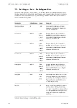
Страница 46: ...e 2 38400 9600 19200 38400 57600 Digital Gateway Serial Interface Port 2 Communication Speed on Modbus RTU link between Digital Gateway and M10x M Baudrate 3 38400 9600 19200 38400 57600 Digital Gateway Serial Interface Port 3 Communication Speed on Modbus RTU link between Digital Gateway and M10x M Baudrate 4 38400 9600 19200 38400 57600 Digital Gateway Serial Interface Port 4 Communication Speed...

Страница 47: ...ateway Parameter Default Value Range Remarks Slave address 1 247 1 247 RTU Slave Address Slave address 2 0 1 247 Only for MNS Digital Upgrade solution for INSUM 1 Slave address 1 define device number 1 to 32 slave address 2 de fine device number 33 to 64 Baud rate 19200 9600 19200 38400 115200 Data Transmission Speed Parity bit Even None Even Odd Used for Error checking Stop bit 1 1 or 2 Required ...

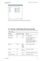
Страница 48: ...mand Format MNSiS MNSiS INSUM 1 INSUM 2 Only for MNS Digital Upgrade solution for INSUM 1 and 2 Support of DCS command format in INSUM 1 INSUM 2 and MNSiS Table 13 Digital Gateway Default Parameters Modbus RTU configuration Configuration of the parameters is done via MNavigate The parameters must then be downloaded to the Digital Gateway f Figure 33 Parameter Window for MODBUS RTU parameters in MN...

Страница 49: ... 100 255 Calculated automatically Default Gateway LAN1 0 0 0 0 Settings according to network ad ministrator Slave address 247 1 247 RTU Slave Address Port 502 502 TCP Port Number PLC Time Out enable No Yes No Activates PLC time out PLC Failsafe Time Out 10 1 100 Delay until Failsafe is activated DCS Command Format MNSiS MNSiS INSUM 1 INSUM 2 Only for MNS Digital Upgrade solu tion for INSUM 1 and 2...

Страница 50: ...lsafe In circumstances where a disturbance in the MODBUS communication network needs to be monitored it is possible to select a Failsafe state for each M10x This state must be de fined as a parameter for each M10x separately The Digital Gateway supervises the MODBUS communication to the PCS or PLC if the parameter PLC Time Out is set to YES The timeout for this connection is set by using the param...

Страница 51: ... be configured before start up Any change of configuration settings on the Digital Gateway requires restart of the Digital Gateway During Digital Gateway restart all communication on the switchgear bus network as well as communication to DCS PLS PLC is stopped After reboot is completed all communications are re established Power On the control voltage supply The Digital Gateway boots automatically...

Страница 52: ...tween master and slave loop back FC16 Pre set multiple Registers Write of several successive words into register file Table 15 Function Codes The Digital Gateway is a standard MODBUS slave device The PLC or PCS master initiates the communication by sending the Query Messages and the Digital Gateway replies the re quested information in Response Messages 8 1 Message Format Query Messages The MODBUS...

Страница 53: ... Control Access Information Alarms Trips The valid address range 10001 19999 8 3 Function Code 03 Read Holding Registers With function code 03 the control system can read the registers that can store the numerical data which can be driven to external devices as mentioned below Measuring Values Status as Word oriented bits Alarm structure Warnings Trips The valid address range 40001 49999 8 4 Funct...

Страница 54: ...float value is as follows Bit Number 15 8 7 0 Register n Data Low High Data Low Low Register n 1 Data High High Data High Low Table 19 Byte representation for Float Big Endian 8 6 Function Code 06 Preset Single Register Function code 06 allows control system to modify the contents of a single output register Any output register that exists within the system can have its contents changed by this me...

Страница 55: ...rom the command control 8 9 Restrictions 8 9 1 General To ensure optimal performance a maximum of 60 modbus requests per second is allowed According Modbus standard Digital Gateway supports up to 16 simultaneous requests Simultaneous means Modbus master don t wait until response of Digital Gateway DCS could send more new requests Please keep in mind DCS has to count open requests and has to check ...

Страница 56: ...query could not be served Exception code 1 Illegal function A Function Code was received that is not supported Exception code 2 Illegal data address A register address is out of the valid range Exception code 3 Illegal data value The length of the telegram is not valid start address register counter start address range 1 Exception code 8 Memory parity error The CRC of the received telegrams is not...

Страница 57: ...ng Tool This is a proprietary tool for ABB to program the MODBUS reg isters according to customer requirements 9 2 Default Data Map Monitoring Inputs from M10x Monitoring of the M10x data handled by the Digital Gateway is possible utilizing the following function codes and address ranges FC 02 10001 19999 Bit registers FC 03 40001 49999 Word registers FC 04 30001 39999 Word registers For LVS Digit...

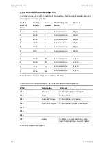
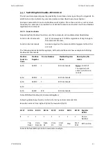
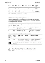
Страница 58: ...vailable comm ok 2 10002 2 Life Bit M10x 2 M10x 2 is available comm ok 2 10003 3 Life Bit M10x 3 M10x 3 is available comm ok 2 10004 4 Life Bit M10x 4 M10x 4 is available comm ok 2 10005 5 Life Bit M10x 5 M10x 5 is available comm ok 2 10006 6 Life Bit M10x 6 M10x 6 is available comm ok 2 10007 7 Life Bit M10x 7 M10x 7 is available comm ok 2 10008 8 Life Bit M10x 8 M10x 8 is available comm ok 2 101...

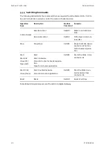
Страница 59: ...able 2 11006 1 Alarm 1 Any Alarm condi tion of protection or supervision functions 2 11007 1 New Trip 1 Any Trip condition of the protection or supervision functions 2 11008 1 Test 1 Main switch set to test position Motor cannot start 2 11009 1 HW local 1 Control Access is selected to hardwired I O from Local Re mote input on M10x 2 11010 1 Bus local 1 Control Access is passed to any control stati...

Страница 60: ...of M10x is on 2 11018 1 DI9 1 Digital Input 9 of M10x is on 2 11019 1 DI10 1 Digital Input 10 of M10x is on 2 11020 1 DI11 1 Digital Input 11 of M10x is on 2 11021 1 DI12 1 Digital Input 12 of M10x is on 2 11022 2 Stopped 1 Motor Stopped or Tripped or Feeder open 2 11023 2 Runs 1 Motor Runs or Feeder closed 2 11024 2 CW or K1 1 Motor Runs Clock wise 2 13668 128 Stopped 1 Motor Stopped or Tripped o...

Страница 61: ...75 128 Test 1 Main switch set to test position Motor cannot start 2 13676 128 HW local 1 Control Access is selected to hardwired I O from Local Re mote input on M10x 2 13677 128 Bus local 1 Control Access is passed to any control station on the switch gear control network 2 13678 128 Remote 1 Control Access is passed to the Process Control System 2 13679 128 DI0 1 Digital Input 0 of M10x is on 2 1...

Страница 62: ...ion Remarks 2 13684 128 DI8 1 Digital Input 8 of M10x is on 2 13685 128 DI9 1 Digital Input 9 of M10x is on 2 13686 128 DI10 1 Digital Input 10 of M10x is on 2 13687 128 DI11 1 Digital Input 11 of M10x is on 2 13688 128 DI12 1 Digital Input 12 of M10x is on Table 21 Default Modbus Map Bit Status of M10x ...

Страница 63: ...2Byte Time before M10x will trip the motor only available if TOL protection function is used 3 40004 1 Time to reset Unsigned Int 2Byte Time required be fore reset allowed only available if TOL protection function is used 3 40005 2 Phase current L1 Unsigned Int 2Byte age L1 Current 3 40006 2 Thermal image Unsigned Int 2Byte Used thermal capacity 3 40509 128 Phase current L1 Unsigned Int 2Byte age ...

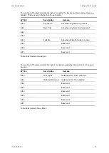
Страница 64: ...tatus 2Byte 3 4100 3 Extended status 2Byte 3 41253 127 Extended status 2 Byte 3 41254 127 Extended status 2 Byte 3 41255 128 Extended status 2 Byte 3 41256 128 Extended status 2 Byte Table 23 Default Modbus Map Extended Status for M10x The content of the Extended Status Byte 1 is described in following table BYTE 1 Description Remark Bit 0 Stopped 1 Motor Stopped or Tripped Bit 1 Runs 1 Motor Runs...

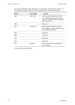
Страница 65: ...s present Bit 2 Bit 3 Bit 4 Failsafe Set when Failsafe mode is active Bit 5 Reserved Bit 6 Reserved Bit 7 Reserved Table 25 Extended Status Byte 2 The content of the Extended Status Byte 3 contains availability information for the power module BYTE 3 Description Remark Bit 0 Test Input Isolator set to Test position Bit 1 Main Switch Input Isolator set to On position Bit 2 Reserved Bit 3 Reserved B...

Страница 66: ...Description Remark Bit 0 HW Local M10x accepts control commands from the hardwired inputs on M10x when the respective Local control in put is set to true Bit 1 Reserved Bit 2 BUS Local M10x accepts control commands from a device on the switchgear con trol network eg MView Bit 3 Reserved Bit 4 Reserved Bit 5 Reserved Bit 6 Reserved Bit 7 Remote M10x accepts control commands from DCS only Table 27 E...

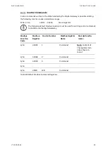
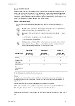
Страница 67: ... 49999 Word registers The following default Modbus registers must be used for writing control commands to the M10x via the Digital Gateway Modbus Function Code Modbus Register Device Number Modbus Register Name Description Re marks 6 16 43001 1 Command Note content of the register indi cates the com mand 6 16 43002 2 Command 6 16 43003 3 Command 6 16 6 16 43128 128 Command Table 28 Default Modbus ...

Страница 68: ... control 0x2104 DCS allows control via local HMI Stop Stop Open 0x0201 Stops the M10x Opens contactor K1 for Con tactor Feeder applica tion Start Start CW Close CF Open Act Start Start Clockwise Close for Contactor Feeder applica tion Open for Actuator application 0x0202 Starts the M10x Close contactor K1 Start CCW Close Close Start Counterclockwise Close for Actuator Application 0x0203 Start the ...

Страница 69: ...tion 16 Commands Are sent only when the command bit is toggled either 0 to 1 or 1 to 0 The following tables detail the registers bit functionalities and show examples of utilizing Modbus bit commands Modbus Function Code Modbus Register Device Number Modbus Register Name Description Re marks 6 16 45001 1 Bit Commands Note content of the register indi cates up to 16 com mands 6 16 45002 2 Bit Comma...

Страница 70: ... Redundancy er ror Table 33 Redundant data for monitoring by the Modbus master Modbus Function Code Modbus Register Modbus Register Name Format Description Remarks 6 16 44001 Force to changeover to Backup Digital Gateway Unsigned In teger 2Byte Master must send 0x0001 to force to changeover This command may be sent to either the Primary or Backup Digital Gateway to initiate a changeover Table 34 R...

Страница 71: ...n panel in switchboard or via web interface like MView Hardware Local M10x switches to the Hardware Local mode and operation is possible only through digital inputs on M10x Hardware Hardware Local must be activated by the setting the input on the M10xl Table 35 Command and Status for Control Access Notes At any time any control station can obtain the control access by sending a control access comm...

Страница 72: ...he M10x is set to HW Local Recommended procedure for sending control commands for a motor starter 1 Set the M10x to Remote with the command 0x2100 2 2 Set the desired state Run Reverse Off Run Forward or Trip Reset 3 Wait until desired state is shown in motor state received from Slave 4 Reset previous command Run Reverse Off Run Forward or Trip Reset ...

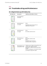
Страница 73: ...al Gateway is Primary in Dual Redundant configuration Digital Gateway is running Ok LED 6 DCS communication active Digital Gateway is running Ok LED6 DCS communication active LED 8 Digital Gateway is Primary in Dual Redundant configuration Digital Gateway miss ing application files Possible cause could be a interrupted or dis turbed communication between MNavigate and Digital Gateway while down lo...

Страница 74: ...Gate way error Digital Gateway is not able to create inter nal database Please reboot the Digital Gateway If that doesn t resolve the problem use MNavi gate to download the Digital Gateway configuration again XML file missing During startup Digital Gateway is checking if all required xml files are available In case of a missing file that error is indicated Please use MNavigate to download the Digi...

Страница 75: ...he Digital Gateway configuration or down load Mapping file again ref to MNavigate Help or MNavigate Manual General DCS fault only available if con figured See above LED 8 Digital Gateway is Primary in Dual Redundant configuration General redundancy fault only available if configured Please use MNavigate to check the redundancy status Redundancy Report If a mismatch was found please download the re...

Страница 76: ... network configuration is correct use a ping command to verify that the Digital Gateway is reachable Open a command window on the PC Start Run then type in cmd and click Enter Enter the ping command with the correct IP address of Digital Gateway ping xxx yyy zzz aaa If no reply is received check the cable connection of the PC or MView and Digital Gateway If a reply is received the connection is ok...

Страница 77: ...l Gate way Check if the correct Modbus RTU Cable connection and termination are all in line with the requirements detailed in the Serial Link connections section Check if the Slave address parameters for RTU is correctly set Check if the parameters for Modbus TCP is correctly set Table 37 Digital Gateway Troubleshooting ...

Страница 78: ......

Страница 79: ... Initial release 2018 05 09 EPDS HE M0202 all 29 Update of device naming Digital Gateway CMES Edge Chapter 6 2 3 Update of drawings 2020 08 13 ELDS FS M0203 07 all Dimension of Digital Gateway corrected chapter 0 Description for support of M10x TCP 2020 10 02 ELDS FS ...

Страница 80: ... Visit us http www abb com mns Document Number 1TGC908004 M0203 ...

Отзывы: