manualshive.com logo in svg
background image


2105824-001 rev. AA

 | 19


2.  Jumper pins 2 and 3 on J12. 

4.8  Reinstall the LevelMaster into the tank 

For additional details and scenarios for reinstalling the sensor into the tank refer to 
the LevelMaster user manual (see the Additional Information section). 
To reinstall the unit: 
1.  Secure the cover back on the electronic enclosure. 
2.  Lift the unit from the floor and prepare to reinsert it into the tank. 
3.  Once positioned for reinsertion, slowly lower the LevelMaster down through the 

hole in the tank. Make sure that the unit is vertical until it is resting on the 
bottom. If there is sludge at the bottom, work the unit up and down a few times 
to reach the bottom. 

4.  Screw the tank port bushing into the tank port opening. 
5.  Tighten the nut on the cord connector. 
6.  Plumb the cable or conduit into the electronics enclosure for the 

communications and power wiring. 

7.  Proceed to restore the field wiring next. 

4.9 Restore 

field 

wiring 

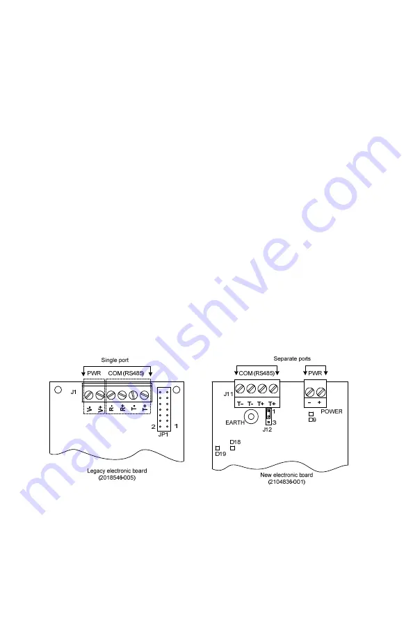
The new electronic headboard has two separate ports for communication and power 
in contrast with the single port on the previous board (Figure 13). 
If a single connector was wired to connect to the previous board, replace it with the 
two connectors that came with the new board and were removed in section 4.4, 

Insert the new electronic board

If two connectors were already in use, rewire the connector for communication. The 
pinout for RS485 in the previous board does not match that of the new board. 


Figure 13: Electronic ports pinouts 

For additional details on the connections to other ABB equipment refer to the 
LevelMaster user manual (see Additional Information section). 

4.9.1  Wiring for power 

To rewire for power: 
1.  Remove the cover from the enclosure. 
2.  Loosen the screws on the power connector (2-position terminal connector). 
 

Содержание LevelMaster 7100

Страница 1: ...g IMPORTANT NOTE This guide does not address any requirements for the removal or installation of product s in hazardous classified locations Refer to the installation instructions and local and nation...

Страница 2: ...xperiencing issues downloading the software call a local ABB representative or call the main office number listed on the back page of this guide Assumptions The following apply to this guide The Level...

Страница 3: ...signal word CAUTION indicates a potentially dangerous situation Failure to observe this safety information may result in property damage The symbol may also be used for minor injury warnings The text...

Страница 4: ...contents are inspected and found to be free of damage CAUTION Equipment damage A static electric discharge can result in damage to the electronic board Wear a grounding strap to eliminate static elec...

Страница 5: ...aging all the installed LevelMasters with MasterLink 2 0 configuration files may be copied to the new installation directory To install 1 Go to the Liquid level sensor LCM7100 page click the Downloads...

Страница 6: ...to perform the upgrade Tools and material Phillips screwdriver Small slotted screwdriver 24 inch pipe wrench Wooden blocks or other means to support the sensor on the floor when removed from the tank...

Страница 7: ...e communication port RS485 to RS232 Converter cable 2100241 002 Contains 2 batteries 9 Vdc Both boards RS232 to USB converter cable Third party manufacturer Use if connecting to a USB port on a laptop...

Страница 8: ...ensor calibration data Figure 2 shows the top of an installed LevelMaster Use as a reference for this procedure TANK PORT BUSHING CORD CONNECTOR TANK ELECTRONICS ENCLOSURE NUT Figure 2 Top of the Leve...

Страница 9: ...If no wooden blocks are available use any stable and even support to keep the unit from rotating while in horizontal position 13 Proceed to replace the existing floats 4 2 Replace the existing floats...

Страница 10: ...Select the laptop communication port used 5 Leave Baud Rate at 9600 It assumed the board was at the default baud rate If not set at the default rate select the other option 1200 6 Click Setup LevelMas...

Страница 11: ...sion IMPORTANT NOTE The default path for the saved file depends on the MasterLink version used The files are automatically saved in the main installation directory of each version Make sure to take no...

Страница 12: ...and forefinger making sure the apex of the arch is placed against the board while the ends of the tab are braced to the inside of the housing 7 Proceed to configure the board 4 5 Configure the new boa...

Страница 13: ...2 Configure the new electronic board with the existing configuration Use this procedure if configuring the new board with the existing configuration file saved in section 4 3 3 Save the configuration...

Страница 14: ...default configuration Use this procedure if configuring the new board with one of the default files included with the MasterLink software Using the default file provides only calibration data for the...

Страница 15: ...AA 15 Figure 7 Downloading correct configuration to the LevelMaster 6 Click Download Data to LevelMaster 7 Click OK when the download is complete 8 Click the Setup tab Figure 8 Figure 8 Configure the...

Страница 16: ...shing communication 11 From the monitor screen verify that the level and temperature readings display expected values based on the float position and temperature See section 4 6 Verify measurements 12...

Страница 17: ...nd New Value 8 Verify that the RS485 termination address is now set to 1 Figure 11 Figure 11 RS485 termination for the last sensor IMPORTANT NOTE The RS485 bus termination value for intermediate Level...

Страница 18: ...ndicate the position of the float s 3 Slide the floats to several positions on the sensor and verify that the screen updates and reflects the correct level for the floats 4 Proceed to ground the unit...

Страница 19: ...r conduit into the electronics enclosure for the communications and power wiring 7 Proceed to restore the field wiring next 4 9 Restore field wiring The new electronic headboard has two separate ports...

Страница 20: ...ource if unable to power the unit from the flow computer or controller 3 Insert the wires in the power connector observing correct polarity Figure 14 a Connect to flow computer remote controller COM p...

Страница 21: ...bus wire as shown in Figure 16 Figure 17 page 22 or Figure 18 page 22 IMPORTANT NOTE Review the Phoenix Contact terminal connection specifications for acceptable wire gauge and type when connecting m...

Страница 22: ...smits signals on the communication port If these LEDs do not lit up check the wiring 4 10 Verify installation using PCCU If the LevelMaster is connected to an ABB Totalflow flow computer or remote con...

Страница 23: ...r counts should display Figure 19 Figure 19 Verify sensor measurements from PCCU 5 Verify that the temperature measurement is the expected value It must reflect the temperature in the tank 6 Verify th...

Страница 24: ...ling Verify converter cable and adaptors are securely attached Verify batteries on converter cable are charged and connected correctly positive voltage terminal must be connected to red wire Install d...

Страница 25: ...es 5 2 2 Measurement errors displayed by the LevelMaster application The errors described in Table 6 display on the LevelMaster Tank number tab If multiple tanks are configured under the LevelMaster a...

Страница 26: ...26 2105824 001 rev AA Figure 20 Measurement errors...

Страница 27: ...2105824 001 rev AA 27 Notes...

Страница 28: ...ginal US English version of this manual shall be deemed the only valid version Translated versions in any other language shall be maintained as accurately as possible Should any discrepancies exist th...

Отзывы: