


4 Repair
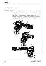
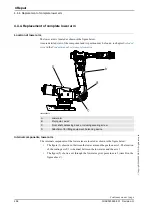
4.4.4. Replacement of complete lower arm
259
3HAC020993-001 Revision: G
©
Co
py
rig
h
t 200
4-
200
8 ABB. All righ
ts reser
v
ed.
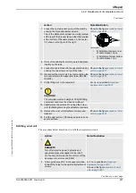
Removal, lower arm
The procedure below details how to remove the complete lower arm.
Action
Note/Illustration
1.
DANGER!
Turn off all electric power, hydraulic and
pneumatic pressure supplies to the robot!
For Foundry Prime robots: Do not turn off the air
pressure to motors and SMB.
2. Remove the upper arm.
.
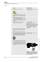
3. Disconnect and remove the cables from inside
the lower arm.
Release any cable attachments.
.
4. Apply the
lifting eye, M12
to the balancing device
and raise to unload the weight of the device.
Attachment is shown in the figure
Location of lower arm on page 256
5. Unload the balancing device in order to make the
piston rod and front ear adjustable when pulling
the front shaft out.
Detailed in section
.
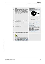
6. Remove the securing screw from the balancing
device
front shaft.
Shown in the figure
.
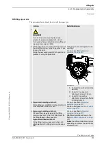
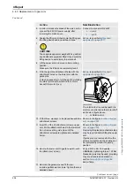
7. Apply the
puller tool, balancing device shaft
to the
shaft of the balancing device, through the hole in
the frame.
The shaft has a M20 thread diameter, as shown
in the figure to the right.
Pull the shaft out using the puller tool and the
hydraulic pump.
xx0300000060
Note!
The dimension of the shaft
puller tool is M20. Do not mix up with
the shaft press tool used when
mounting the shaft.
8. Lower the balancing device until it rests safely
against the bottom of the frame.
Continued
Continues on next page
Содержание IRB 6650S - 200/3.0
Страница 2: ......
Страница 9: ...Table of Contents 7 3HAC020993 001 Revision G Copyright 2004 2008 ABB All rights reserved ...
Страница 10: ...Table of Contents 8 3HAC020993 001 Revision G Copyright 2004 2008 ABB All rights reserved ...
Страница 18: ...How to read the product manual 3HAC020993 001 Revision G 16 Copyright 2004 2008 ABB All rights reserved ...
Страница 366: ...4 Repair 4 7 4 Replacement of gearbox axis 6 3HAC020993 001 Revision G 364 Copyright 2004 2008 ABB All rights reserved ...
Страница 456: ... Copyright 2004 2006 ABB All rights reserved Revision 02 sheet Circuit Diagram 3HAC 13347 1 Contents 101 ...
Страница 458: ... Copyright 2004 2006 ABB All rights reserved Revision 02 sheet Circuit Diagram 3HAC 13347 1 Legend 103 ...
Страница 459: ... Copyright 2004 2006 ABB All rights reserved Revision 02 sheet Circuit Diagram 3HAC 13347 1 Brake Release Unit 104 ...
Страница 461: ... Copyright 2004 2006 ABB All rights reserved Revision 02 sheet Circuit Diagram 3HAC 13347 1 Axis 1 106 ...
Страница 462: ... Copyright 2004 2006 ABB All rights reserved Revision 02 sheet Circuit Diagram 3HAC 13347 1 Axis 2 107 ...
Страница 463: ... Copyright 2004 2006 ABB All rights reserved Revision 02 sheet Circuit Diagram 3HAC 13347 1 Axis 3 108 ...
Страница 464: ... Copyright 2004 2006 ABB All rights reserved Revision 02 sheet Circuit Diagram 3HAC 13347 1 Axis 4 109 ...
Страница 465: ... Copyright 2004 2006 ABB All rights reserved Revision 02 sheet Circuit Diagram 3HAC 13347 1 Axis 5 IRB 7600 110 ...
Страница 466: ... Copyright 2004 2006 ABB All rights reserved Revision 02 sheet Circuit Diagram 3HAC 13347 1 Axis 6 111 ...
Страница 467: ... Copyright 2004 2006 ABB All rights reserved Revision 02 sheet Circuit Diagram 3HAC 13347 1 Switches axis 1 113 ...
Страница 468: ... Copyright 2004 2006 ABB All rights reserved Revision 02 sheet Circuit Diagram 3HAC 13347 1 Switches Fan axis 2 114 ...
Страница 469: ... Copyright 2004 2006 ABB All rights reserved Revision 02 sheet Circuit Diagram 3HAC 13347 1 Switches Fan axis 3 115 ...
Страница 470: ... Copyright 2004 2006 ABB All rights reserved Revision 02 sheet Circuit Diagram 3HAC 13347 1 Axis 5 IRB 6600 901 ...
Страница 471: ... Copyright 2004 2006 ABB All rights reserved Revision 02 sheet Circuit Diagram 3HAC 13347 1 Design changes note 1 1 905 ...
Страница 476: ......


