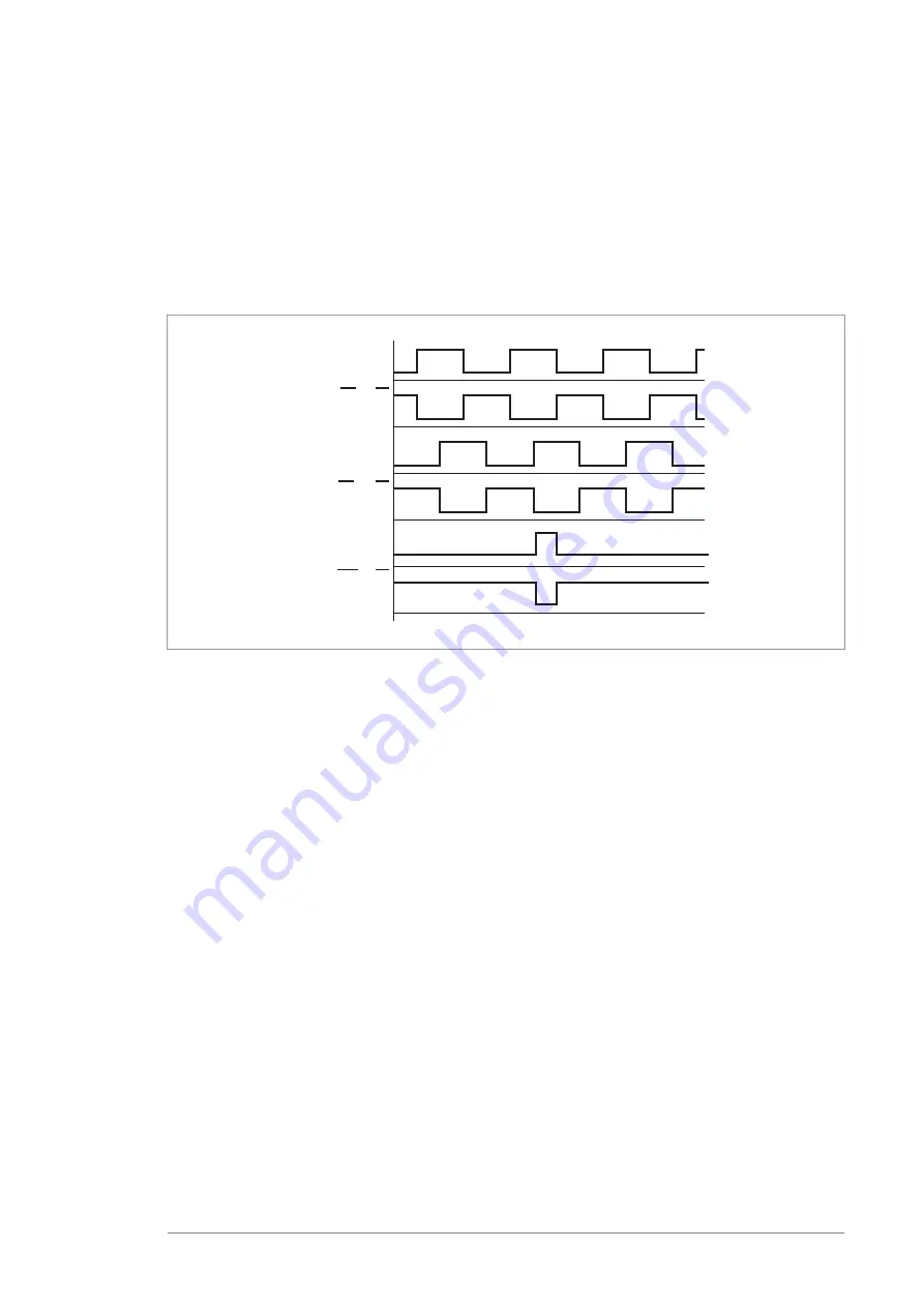
General encoder phasing principle
When the encoder is connected correctly, running the drive in the Forward (positive
speed reference) direction should produce a positive encoder feedback.
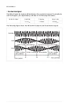
On incremental encoders, the two output channels, usually marked 1 and 2 or A and
B, are 90° (electrical) apart from each other. When rotated clockwise, most encoders
have channel 1 leading channel 2 as illustrated below. Determine the leading channel
by referring to the encoder documentation or by measuring with an oscilloscope.
A+ or A or 1
A- or A or 1
B+ or B or 2
B- or B or 2
Z+ or Z or 0
Z- or Z or 0
The encoder output channel that leads when the drive runs Forward should be
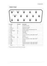
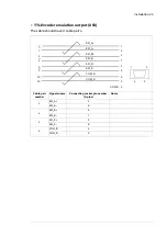
connected to FEN-21 input A, the output channel that trails to FEN-21 input B.
The zero reference output channel (usually marked 0, N or Z) needs to be connected
in positioning applications only.
Installation 27


