■
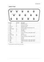
Resolver input (X52)
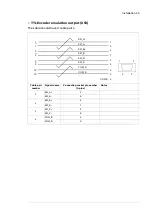
The cable should have 4 twisted pairs. Additional 0V and GND pins are reserved for
connecting cable shields. The shields should be connected either to 0V or to GND
(chassis). Connection of the shields to GND (chassis) can also be made through the
D-connector hood cable clamping.
5
15
10
10
3
4
9
12
13
8
11
14
15
6
6
SIN+
1
1
2
2
EXCITATION
EXCITATION
SENSOR
0V
0V
0V
0V
GND
GND
GND
GND
SIN-
COS+
COS-
EXC
EXCITATION-
PTC/KTY-84
PTC/KTY_0V
11
1
1
7
2
5
Notes
Connecting plug pin
number (9-pins)
Signals name
Cable pair number
6
SIN+
1
1
SIN-
7
COS+
2
2
COS-
5
EXC
3
10
EXCITATION-
Temperature sensor
3
PTC/KTY-84
4
Temperature sensor, return
4
PTC/KTY_0V
Shield/optional
9
COM_B
Twisted pair shields
connected to 0V
Shield/optional
12
COM_B
Shield/optional
13
COM_B
Shield/optional
8
GND
Twisted pair shields
connected to GND
(chassis)
Shield/optional
11
GND
Shield/optional
14
GND
Shield/optional
15
GND
Installation 23


