
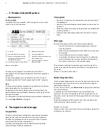


FAM3200
ARMORED VARIABLE AREA PURGEMETER | CI/FAM3200-EN REV. D
9
Solids content in the measuring medium
Variable area flowmeters have only limited suitability for
measuring media containing solids.
Depending on the concentration, particle size and type of solid,
increased mechanical abrasion may occur, especially at the
critical measuring edge of the float.
In addition, solidified deposits on the float can change its weight
and shape.
These effects can lead to erroneous measurement results,
depending on the float type.
In general, the use of appropriate filters is recommended in such
applications.
For the flow measurement of measuring media containing
magnetic particles, we recommend the installation of a
magnetic separator upstream of the variable area flowmeter.
Mounting
General information
The flowmeters in the FAM3200 series are intended for vertical
pipe mounting.
The following points must be observed during installation in the
piping:
• The measuring medium must flow from bottom to top.
• The piping may not exert any inadmissible forces or
torques on the device The device must be disconnected
from the power supply for installation.
• Use gaskets made from a material that is compatible
with the measuring medium and measuring medium
temperature.
• Gaskets must not extend into the flow area, since
possible turbulence could influence the accuracy of the
device
Flowmeter installation
Install the flowmeter centrally in the piping at the required
position using the correct threaded connections.
When tightening the process connections on the flowmeter, use
a spanner of the corresponding size to counter the force.
Model
Meter size
Wrench size [mm]
FAM3220 / FAM3250
¼ in
SW 22
FAM3225 / FAM3255
¼ in
SW 19
⅜
in
SW 24
½ in
SW 27
1 in
SW 50
Check the process connections for tightness.
6
Electrical connections
Analog indicator with alarm signaling unit
Specifications
Operating mode
bistable
Switching function
NAMUR contact
Nominal voltage
8 V DC (Ri approx. 1 k
Ω
)
Operating voltage
5 to 25 V DC
Switching frequency
Maximum 5 kHz
Connection type
Cable, 2-
wire, brown (+) / blue (−), length
1.75 m (5.74 ft)*
Switching point single alarm
Minimum 0 to 60 %
Maximum 40 to 100 %
Switching point double alarm
Minimum setting range approx. 5 %
Setting accuracy
±2 % of measured value
Repeatability
±0.5% of scale end value
* Other cable lengths available on request.
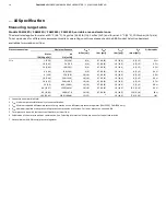
Temperature and electrical data
The following table shows the maximum permitted measuring
medium temperature T
medium
and the permitted electrical data
depending on the ambient temperature T
ambient
and the gasket
material.
Ambient temperature T
ambient
40 °C (104 °F)
50 °C (122 °F)
60 °C (140 °F)
System bus, computer
interfaces
T
medium
maximum [°C (°F)]
I
i
[mA]
P
i
[mW]
A
B
A
B
A
B
25
34
100 (212)
180
(356)
100 (212) 165 (329) 100 (212)
155
(311)
25
64
100 (212)
180
(356)
100 (212) 165 (329) 100 (212)
155
(311)
52
169
100 (212) 130 (266) 100 (212)
115
(239)
100 (212) 100 (212)
76
242
80
(176)
80
(176)
65
(149)
65
(149)
50
(122)
50
(122)
A
Gasket material Buna N®
B
Gasket material Viton A® / Kalrez®


