48
48
7.6. HMI installation instructions
1) Drill the panel according to the HMI dimensional drawing
(the dimensions are given in mm).
2) Drill the 4 holes for the M4 screws to fix the HMI.
3) Assemble the HMI using M4 screws and tighten the screws
appropriately.
4) Fit the earthing cable in the special connector using M4
type screws.
For the HMI earthing connection use a copper braid cable
of Round Multistrand Cable type. Make sure that there
is no paint, rust or anything else on the contact surface
between the cable and the connector of the special HMI.
Connect the other end of the cable to a safe earthing point
of the switchgear.
5) Fit the communication cable in the special HMI connector 9
PIN -DSUB (-XDB31).
The serial cable is supplied with the eVD4 socket Kit.
6) Assemble the two-pole power supply connector of the HMI
(-XDB32).
Note:
The HMI can be supplied both in direct current and in
alternating current (V = 48 ... 250 V d.c./a.c.).
The racking-in operation can only be carried out with the
circuit-breaker open.
Note
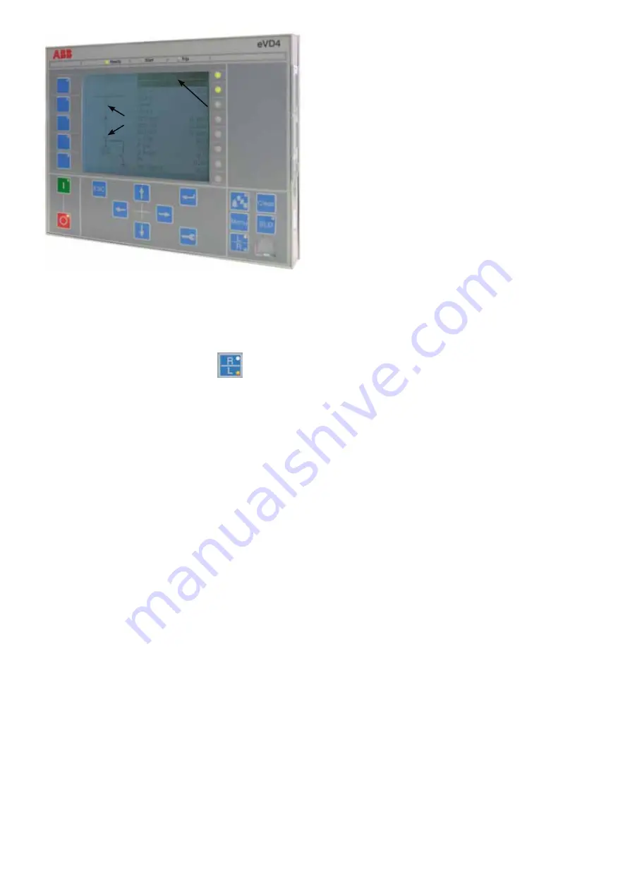
Make sure that the control mode is set to “Local”
(the LED alongside the letter L on button
must be
on), otherwise press the control mode selection button until
the LED alongside L comes on.
After having carried out the instructions in points a), b), c) and
d), comply with the following indications to open the circuit-
breaker:
i) select SLD, with the SLD button
j) select the truck symbol by means of the arrow button
k) press the green button “I” to rack-in the circuit-breaker
l) confirm the racking-in
operation with the “enter” arrow
button
The truck motor is activated causing circuit-breaker racking-
in. The truck symbol in the SLD will consequently be updated.
The right-hand side of the display dedicated to the menu will
now be active again.
Содержание eVD4
Страница 2: ......
Страница 47: ...45 45 eVD4 N eVD4 N eVD4 N eVD4 Fig 8b Fig 8c Fig 8d Fig 8e ...
Страница 68: ...66 66 74 60 89 10 160 10 58 2 106 5 58 2 17 51 180 34 5 223 HM1 ...
Страница 70: ...68 68 ...
Страница 71: ......


