46
46
7.3. Preliminary operations
– Clean the insulating parts with clean dry cloths.
– Check that the top and bottom terminals are clean and
free of any deformation caused by shocks received during
transport or storage.
7.4. Installation of fixed circuit-breakers
The circuit-breaker can be mounted directly on supporting
frames to be provided by the customer, or on a special
supporting truck (available on request).
The circuit-breaker, with supporting truck, must be suitably
fixed to the floor of its compartment by the customer.
The truck wheels must run on a carefully levelled surface.
A minimum degree of protection (IP2X) must be guaranteed
from the front towards live parts.
7.5. Installation of withdrawable circuit-
breakers in UniGear ZS1 switchgear
and PowerCube units
The withdrawable circuit-breakers are pre-engineered for use
in UniGear ZS1 switchgear and PowerCube units.
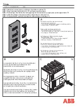
For racking-in/racking-out of the switchgear, fully insert the
lever (1) (fig. 9) in the appropriate seat (2) and turn it
clockwise for racking-in, and anti-clockwise for racking-out,
until the end of travel positions are reached.
Circuit-breaker racking-in/-out must be carried out gradually
to avoid shocks which may deform the mechanical interlocks
and the limit switches.
The torque normally required to carry out racking-in and
racking-out is <25 Nm.
This value must not be exceeded. If operations are prevented
or difficult, do not force them and check that the operating
sequence is correct.
Nota
To complete the racking-in/out operation, about 20 rotations of the lever are re-
quired for circuit-breakers up to 17,5 kV – pole centre distance 150 mm and about
15 for circuit-breakers up to 17,5 kV – pole centre distance 210-275 mm.
When the circuit-breaker has reached the isolated for test/
isolated position, it can be considered in switchgear and
earthed by means of the truck wheels.
Withdrawable circuit-breakers of the same version, and
therefore with the same dimensions, are interchangeable.
However, when, for example, different electrical accessory
fittings are provided, a different code for the plug of the
auxiliary circuits prevents incorrect combinations between
panels and circuit-breakers.
For the circuit-breaker installation operations, also refer to the
technical documentation of the above-mentioned switchgear.
• The racking-in/-out operations must always be
carried out with the circuit-breaker open.
• When putting into service for the first time, it is
advisable to charge the circuit-breaker operating
mechanisms manually so as not to overload the
auxiliary power supply circuit.
7.5.1. Circuit-breakers with withdrawable motorized truck
Carry out the racking-in/racking-out test of the motorized
truck in the same way as for a manual truck, following the
instructions below:
– Rack the circuit-breaker into the switchgear in the open and
isolated position, with the power supply to the motor circuit
cut off and with the enclosure door closed.
– Insert the manual racking-in lever (1) in the special coupling
(2) Fig. 9, and take the motorized truck to about half its run
between the isolated for test and the connected position.
The torque required for truck handling is < 25 Nm. In the
case of accidental reversal of the truck motor power supply
polarity, this operation allows a possible error in
direction to be dealt with without any damage.
Verification checks:
a) motor rotation
clockwise
during circuit-breaker racking-in.
b)motor rotation
anticlockwise
during circuit-breaker racking-
out.
– Remove the manual lever (1) from the coupling (2) Fig. 9
– Power the truck motor circuit.
– Activate the control for the electrical racking-in operation.
When racking-in has taken place, check correct changeover
of the relative auxiliary contact.
– On completion, activate the control for the electrical
racking-out operation. When racking-out has taken place,
check correct changeover of the relative auxiliary contact.
– If there is a motor fault during a racking-in or racking-out
operation, in an emergency the truck can be taken to the
end of its run manually, after first cutting off the power
supply to the motor power supply circuit and then, using
the manual lever, work in the same way as with the manual
truck.
• By means of the chain transmission, truck
handling carried out using the manual lever
makes the truck motor armature rotate which,
behaving like a generator, can cause inverse
voltage at the connection terminals.
• This may damage the permanent magnet of the
motor, therefore all the truck racking-in and
racking-out operations carried out using the
manual lever must be done without power in the
motor circuit.
Содержание eVD4
Страница 2: ......
Страница 47: ...45 45 eVD4 N eVD4 N eVD4 N eVD4 Fig 8b Fig 8c Fig 8d Fig 8e ...
Страница 68: ...66 66 74 60 89 10 160 10 58 2 106 5 58 2 17 51 180 34 5 223 HM1 ...
Страница 70: ...68 68 ...
Страница 71: ......


