41-116.1A
8
a) Contact Wipe – Adjust the stationary contacts
so that both stationary contacts make with the
moving contacts simultaneously and wipe 1/4”
to 3/64” when the armature is against the core.
This can be accomplished by inserting a .0125
thick gage between the armature and case and
adjusting the stationary contacts until they just
touch the moulding.
b) Target – Manually raise the moving contacts and
check to see that the target drops at the same
time as the contacts make or up to 1/16” ahead.
The cover may be removed and the tab holding
the target reformed slightly if necessary. How-
ever, care should be exercised so that the target
will not drop with a slight jar.
c)
Pickup – Place tap screw in the 6 to 20 tap and
turn the core screw all the way in. contacts
should pickup at a value of current less than 6
amperes but not lower than 5.1 amperes. If
pickup is above this range, it may be reduced by
using a tweezer or similar tool and squeezing
each leaf spring approximately equal by applying
the tweezer between the leaf spring and the front
surface of the cover at the bottom of the lower
window. If the pickup is below range it may be
increased by removing the front cover and bend-
ing the leaf spring outward equally. an approxi-
mate adjustment would be when the end of the
leaf spring is in line with the edge of the molded
cover. The described pickup is obtained by set-
ting the tap screw in the proper range and adjust-
ing the core screw.
7.4. Voltage Unit (V)
A. The upper pin bearing should be screwed down
until there is approximately. 0.25” clearance
between it and the top of shaft bearing. The
upper pin bearing should then be securely locked
into position with the lock nut. The lower bearing
position is fixed and cannot be adjusted.
B. The contact gap adjustment for the directional
unit is made as follows:
With the moving contact in the normally-closed
position i.e., against the left stop on bridge,
screw in the stationary contact until both con-
tacts just close as indicated by a neon lamp in
the contact circuit. Then, screw the stationary
contact in toward the moving contact an addi-
tional one-half turn. The clamp holding the sta-
tionary contact housing need not be loosened for
the adjustment since the clamp utilizes a spring-
type action in holding the stationary contact in
position.
C. The sensitivity adjustment is made in two steps:
1) The adjustable resistor, located at the top left
of the voltage unit, is adjusted such that the
maximum resistance is in the circuit (approxi-
mately 2500 ohm).
2) The tension of the spiral spring, attached to
the moving element assembly, is then varied.
The spring is adjusted by placing a screw-
driver or similar tool into one of the notches
located on the periphery of the spring
adjuster and rotating it. The spring adjuster is
located on the underside of the bridge and is
held in place by a spring type clamp that does
not have to be loosened prior to making the
necessary adjustments.
The spring is to be adjusted such that the contacts
will close (indicated by pickup of telephone relay “T”)
when the applied voltage is reduced to 80 volts. The
contacts should open with 80 plus volts applied.
Any setting other than the 80 volts then can be made
by adjusting the resistor for the desired contact clos-
ing voltage.
8. RENEWAL PARTS
Repair work can be done most satisfactorily at the
factory. However, interchangeable parts can be fur-
nished to the customers who are equipped for doing
repair work. When ordering parts, always give the
complete nameplate data.
Class 1E certification of a repaired relay is the
responsibility of the agent who makes the repair.
Содержание COV-11
Страница 12: ......
Страница 13: ......
Страница 14: ......
Страница 15: ......
Страница 16: ......
Страница 17: ......
Страница 18: ......
Страница 19: ......
Страница 20: ......
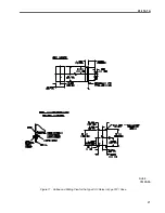
Страница 21: ...41 116 1A 21 Figure 11 Outline and Drilling Plan for the Type COV Relay in Type FT21 Case 3519A66 Sub 4 ...


