manualshive.com logo in svg
background image

— 

ABB ME A SUREMENT & ANALY TICS | USER GUIDE

ControlMaster CM30, CM50 and CMF310

Universal process controllers –  
¼, ½ DIN and fieldmount

Measurement made easy

User Guide – Extended / Dual Functionality IM/CM/ED–EN Rev. X

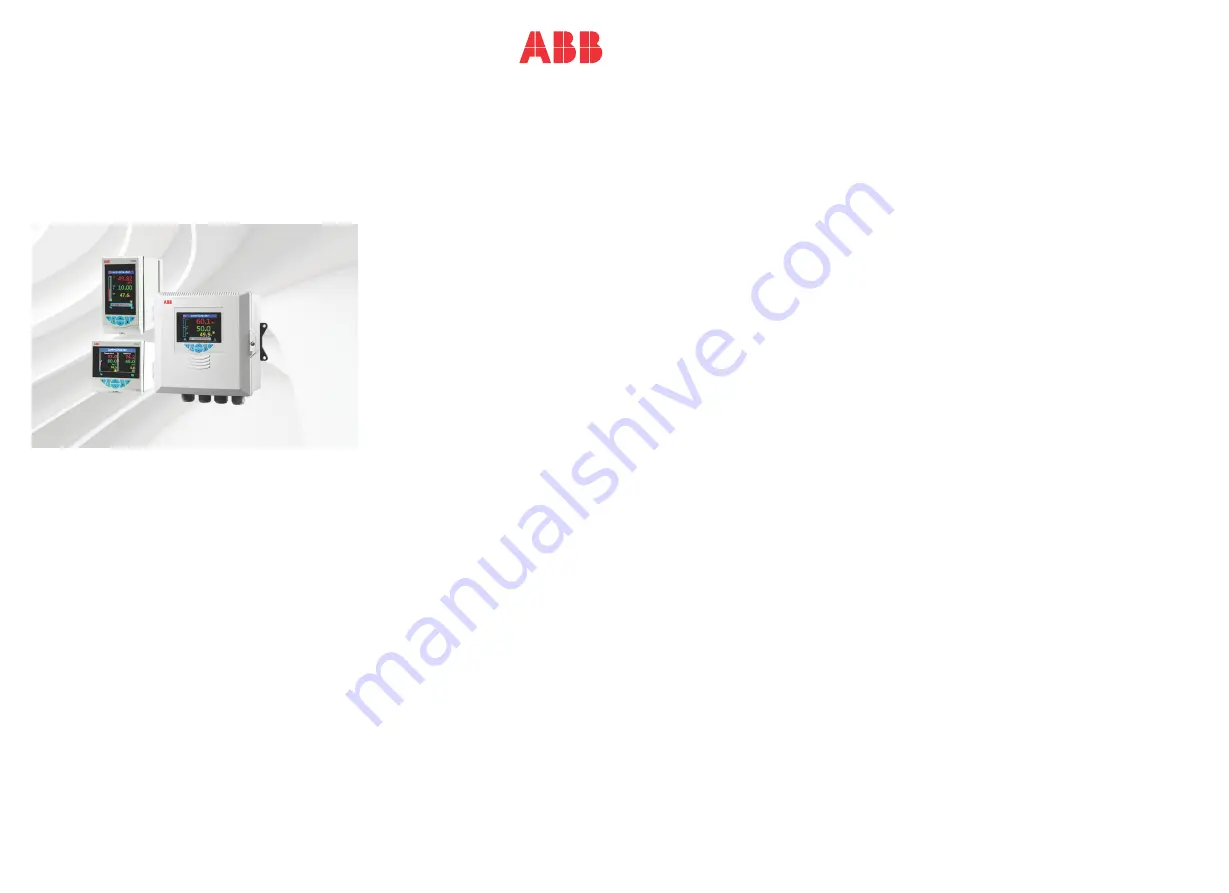
ControlMaster CM30, CM50 and CMF310

Universal process controllers, 

1

/

4

1

/

2

 DIN and 

fieldmount

The Company

We are an established world force in the design and manufacture of instrumentation for industrial 
process control, flow measurement, gas and liquid analysis and environmental applications.
As a part of ABB, a world leader in process automation technology, we offer customers application 
expertise, service and support worldwide.
We are committed to teamwork, high quality manufacturing, advanced technology and unrivalled 
service and support.
The quality, accuracy and performance of the Company's products result from over 100 years 
experience, combined with a continuous program of innovative design and development to 
incorporate the latest technology.

Содержание ControlMaster CM30

Страница 1: ...instrumentation for industrial process control flow measurement gas and liquid analysis and environmental applications As a part of ABB a world leader in process automation technology we offer customers application expertise service and support worldwide We are committed to teamwork high quality manufacturing advanced technology and unrivalled service and support The quality accuracy and performan...

Страница 2: ...ard Adaptive Control Misc Loop 1 2 Output Limits Failure Actions A M Select Sources Slew Rate Tracking Loop 1 2 Split O P Min Input 1 2 Min OP 1 2 Max Input 1 2 Max OP 1 2 Loop 1 2 Valve Ratio Bias Deadband Travel time Loop 1 2 Time Prop Cycle Time 1 2 Output Switching Switch Enable Switch Source Alarm 1 8 Type Tag Source Trip Hysteresis Time Hysteresis Display Enable Acknowledge Source Enable Sou...

Страница 3: ...ntroller 12 4 4 Jumper Links for Relay Outputs CM30 and CM50 Controllers 13 4 4 1 Removing the Controller from its Case CM30 and CM50 13 4 4 2 Resetting Jumper Links CM30 and CM50 13 4 5 Accessing the Connection Board CMF310 Controller 14 4 6 Electrical Connections 15 4 6 1 CM30 Electrical Connections 16 4 6 2 CM50 Electrical Connections 17 4 6 3 Analog Inputs CM30 and CM50 Controllers 18 4 6 4 Di...

Страница 4: ...tation Low Signal Selection Digital Signal Selection 89 8 2 2 Analog Backup Station Low Signal Selection Digital Signal Selection 90 8 2 3 Single Indicator 91 8 2 4 Dual Indicator 91 8 3 Extended Templates 92 8 3 1 Feedforward Feedforward with Remote Setpoints 92 8 3 2 Cascade Cascade with Remote Setpoints 92 8 3 3 Cascade with Feedforward 93 8 3 4 Ratio Controller Internal External Ratio 94 8 3 5...

Страница 5: ...Health Safety Warning Refer to the manual for instructions Direct current supply only Caution Risk of electric shock Alternating current supply only Functional earth ground terminal Both direct and alternating current supply Protective earth ground terminal The equipment is protected through double insulation Health and Safety To ensure that our products are safe and without risk to health the fol...

Страница 6: ...quipment must be installed in accordance with the pertinent clauses of the National Electrical Code and or Canadian Electrical Code for hazardous locations The terminal cover retaining screw must be tightened to a torque of 50 cN m WARNING Explosion hazard Substitution of components may impair suitability for class I division 2 2 4 UL Class I Division 2 CMF310 si commandé Cet équipement est adapté...

Страница 7: ...e shown in Fig 3 1 Fig 3 1 ControlMaster Displays and Icons PV Value Bargraph Setpoint Value Icons Access Level Manual Mode Local Setpoint Remote Setpoint Output Value Auto Mode Operator Level Menu Process Alarm Autotune Feedforward Totalizer Running Adjust Indicates which value is adjusted by the keys Totalizer Stopped Adaptive Gain CM30 and CMF310 Displays CM50 Display Profile Setpoint ...

Страница 8: ...ee page 23 2 Local Remote setpoint mode selection key 3 Up Down keys navigate up down menus and increase decrease displayed values 4 Auto Manual control mode selection key 5 Navigation key right programmable Soft Key see page 38 Fig 3 2 Front Panel Keys Note When a Soft Key option is assigned to key 5 the Advanced Level see page 34 must be accessed using the Operator Level access key 1 a b c d e ...

Страница 9: ...lkie talkies are used connect using screened cables within grounded metal conduit Fig 4 1 Siting Applicable to CM30 CM50 and CMF310 CM50 Shown for Example Only Fig 4 2 Environmental Requirements Applicable to CM30 CM50 and CMF310 CM50 Shown for Example Only At Eye Level Close to the Sensor Avoid Vibration Sensor Temperature Limits 55 C 131 F Max 0 C 32 F Min Humidity Limits 0 to 95 RH CM30 CM50 IP...

Страница 10: ... mm in Fig 4 3 ControlMaster CM30 Dimensions Dimensions in mm in Fig 4 4 ControlMaster CM50 Dimensions Controllers can be close stacked to DIN 43835 97 3 8 97 3 8 121 4 8 141 5 5 91 8 3 6 20 0 8 92 3 6 0 03 0 0 8 0 9 3 6 14 0 55 30 1 18 0 8 0 0 03 0 Controllers can be close stacked to DIN 43835 144 5 6 123 4 9 146 5 7 137 8 5 4 23 0 9 138 5 4 30 1 18 14 0 55 0 04 0 1 0 0 0 03 0 0 7 0 68 2 7 76 3 0...

Страница 11: ...ller Panel Pipe and Wall mount Dimensions Dimensions in mm in To DIN43700 150 mm 6 in if optional cable glands fitted Fig 4 5 ControlMaster CMF310 Panel mount Option 92 3 6 35 1 4 Mounting Panel Maximum Thickness 6 0 236 Cable Gland Kit Optional 40 1 57 40 1 57 7 32 0 04 0 1 1 0 186 7 32 0 04 0 1 1 0 186 Panel Cut out Dimensions 213 8 38 194 7 64 ...

Страница 12: ...t 4 Installation 10 IM CM ED EN Rev X Dimensions in mm in Fig 4 6 ControlMaster CMF310 Pipe mount Option 213 8 38 194 7 64 Cable Gland Kit Optional Pipe Diameters Max 62 2 44 min 45 1 77 Pipe mount Kit Optional CM40 0700 Vertical Configuration Horizontal Configuration 170 6 70 98 3 85 66 2 6 ...

Страница 13: ...Wall mount Installations Dimensions in mm in Fig 4 7 ControlMaster CMF310 Wall mount Option Dimensions in mm in Fig 4 8 ControlMaster CMF310 Weathershield CM40 0702 Pipe and Wall mount CM40 0700 Options 214 8 42 62 2 44 66 2 40 200 7 87 Fixing Centers Ø6 4 0 25 Fixing centers Cable Gland Kit Optional 175 6 89 240 9 45 240 9 45 Wall mount Entries Pipe mount Entries ...

Страница 14: ... E and panel clamp anchor F 4 3 2 CMF310 Controller ControlMaster CMF310 controllers can be panel pipe or wall mounted For NEMA4X protection a panel thickness of 6 mm 0 236 in is required For pipe mount details see Fig 4 6 page 10 For wall mount details see Fig 4 7 page 11 To panel mount the CMF310 controller 1 Cut a hole of the correct size for the controller in the panel see page 9 for cut out d...

Страница 15: ...ng Jumper Links CM30 and CM50 1 The links associated with the relay outputs are shown in Fig 4 12 2 If necessary move the link to select the relay action required N O or N C Note If the bezel release tool is mislaid 2 small flat headed screwdrivers 4 mm 0 15 in can be used as alternative tools one inserted into the front panel slot and the second for leverage in the notch on the underside of the c...

Страница 16: ... cover 2 Turn the connection board cover plate retaining screw B anti clockwise until the cover plate C can be removed 3 Make connections to connection board terminals see Fig 4 19 page 20 4 Refit cover plate C and secure it by turning retaining screw B clockwise until finger tight Close the door and turn door retaining screw A 1 4 turn clockwise to secure Note Before fitting cable glands identify...

Страница 17: ...rough double insulation Insulation Class II CMF310 Insulation Class 1 Analog digital inputs and outputs transmitter power supply and DC power supply are SELV Safety Extra Low Voltage circuits All connections to secondary circuits must have basic insulation After installation there must be no access to live parts for example terminals Terminals for external circuits are for use with equipment with ...

Страница 18: ...Line 100 to 240 V AC 10 W 10 to 36 V DC Rear View Rear View Rear View Option Board 1 Option Board 2 Standard Connections Digital Output External NC C NO Analog Digital Output 1 Digital Input Output 4 Digital Output External Digital Input Output 1 Analog Output 2 Digital Input Output 2 Digital Input Output C C C Relay Output 2 Relay Output 3 Relay Output 4 Neutral Refer to rear panel for MODBUS con...

Страница 19: ...y Output 3 Relay Output 4 Analog Output 2 Comms Option Board 1 Standard Connections C C Analog Input 4 Analog Input 3 Refer to rear panel for MODBUS connections N O factory default or N C contact selection made via internal jumper links see page 13 200 mA Type T fuse mains AC or 2 A Type T fuse 120 V DC max and external isolating switch For UL marked controllers the fuse must be UL recognized Prov...

Страница 20: ...rizer is selected Analog Input 2 can be used only with THC inputs if Analog Input 1 is also used as a THC input For mA input types to ensure loop continuity when the controller is switched off fit a 2V7 Zener diode as shown Note 3 lead RTD 3 leads must have equal resistance not exceeding 20 each mA mV V Digital Input Using internal transmitter power supply Fit the CJ sensor supplied if Analog Inpu...

Страница 21: ...Open Collector Digital Output Connections CM30 and CM50 Controllers Load ve ve Digital Input Output External CM30 Terminal 43 or 35 CM50 Terminal 7 or 30 Digital Input Output CM30 Terminal 44 or 45 36 37 38 or 39 CM50 Terminal 8 or 9 31 32 33 or 34 Digital Input Output CM30 Terminal 46 or 40 CM50 Terminal 10 or 35 Terminal Connections on Standard and Option Boards External Voltage Max 30 VDC 24 VD...

Страница 22: ...M N C N C COM N C N C COM N C N C COM N C COMMUNICATIONS MODULE I O MODULE 2 I O MODULE 3 SK1 SK4 SK5 SK2 1 2 3 4 5 I O MODULE 3 SK5 RELAY 5 OUT 3 OUT 4 RELAY 6 COM N C COM N C I O MODULE 3 SK5 RELAY 5 OUT 3 OUT 4 RELAY 6 COM N C COM N C 3 4 5 Digital I O connections Analog input module 1 terminal connections Optional communications module Ethernet MODBUS Comms connections Analog output connection...

Страница 23: ... put LK3 into position B To disconnect the CJ put LK3 into position A For mA input types to ensure loop continuity when the CMF310 controller or CMF160 indicator is switched off fit a 2V7 Zener diode Note 3 lead RTD 3 leads must have equal resistance not exceeding 20 each Fig 4 20 Analog Inputs 1 and 2 CMF310 Controllers 1 2 3 LK3 4 5 6 A B Transmitter PSU Analog Input 2 Analog Input 1 THC mA mV V...

Страница 24: ...pe options Fig 4 21 Digital Input Output Relays and Analog Output Connections CMF310 Controllers Note This input is designed primarily for use with flowmeters Fig 4 22 Frequency Pulse Input All Controllers N O Relays 1 to 4 COM N C Relays 5 and 6 INT 24 V 100 mA Max Analog Outputs 1 to 4 Digital Input 24 Volt Digital Input Voltage free Load Load Load Chart Recorder COM N C L N L N L INT 24 V DIO 1...

Страница 25: ...urrent adjustable selection Setpoint Select Selects the local setpoint to be used displayed only if more than 1 local setpoint is configured Alarm Acknowledge Acknowledges any active but unacknowledged alarms View Select Selects the Operator view to be displayed Enter Config Level Displays the Access Level selection views see Section 5 4 page 24 for security options Profile Displays the Profile Le...

Страница 26: ...gnostic Description Alarm Tag High High Alarm High Alarm PV1 Failed Level Access Logout Displayed after Basic or Advanced level are accessed Logs the user out of Basic or Advanced level If passwords are set a password must be entered to access these levels again after selecting Logout Read Only Enables all parameter settings to be viewed Basic Enables access to the Basic level and adjustment of PI...

Страница 27: ... Stop Stop a profile program that is running Reset Restart the profile from the beginning of the program Hold Pause the currently running program Operator Hold Skip Segment Abandon the current segment and start the next segment Repeat Segment Return to the beginning of the current segment Fast Run Mode Run the profile 8 times faster than normal rate Table 5 3 Profile Operator page menu functions 4...

Страница 28: ... s 1 ControlMaster Program name ControlMaster Program name Program start time Program end time Program elapsed time Display additional profile information PV CSPT deviation Program icon Program status icon Run Stop Hold Process variable Conrol setpoint Adjustable only when profile is not running Process setpoint active Auto Manual status Program name Adjustable only when profile is not running Tim...

Страница 29: ...n 04 09 33 09 30 0 1 004 57h m 86 000 1 PV 1 2 3 4 5 6 7 8 Current segment Total segments in program Time remaining in segment Segment target setpoint Segment type Ramp rate Display additional profile information Segment event status shown with event 4 active PV event shown inactive Timed event shown active User value ControlMaster ControlMaster Ramp Program name Program name Profile Control Segme...

Страница 30: ...only if the template selected has remote setpoint or if a ratio controller station template is selected see page 94 RSP Bias Sets the remote setpoint bias in engineering units Note This parameter is available only if template selected has remote setpoint or ratio Ramp Mode The ramping setpoint facility can be used to prevent a large disturbance to the control output when the setpoint value is chan...

Страница 31: ...Note To achieve the best results from Autotune switch the controller to Manual control mode see page 6 and adjust the output until the PV is stable close to the normal setpoint before initiating Autotune Autotune Operation The Autotune sequence is shown in the following figure PV PV ON OFF Reverse Acting Control Output Setpoint Hysteresis Value Hysteresis Value Setpoint Direct Acting Control Outpu...

Страница 32: ... to facilitate Gain Scheduling control see page 50 When Gain Scheduling is not enabled the first set of PID parameters only are used Proportional Band 1 Set as of engineering range Integral Time 1 Set in seconds per repeat To turn integral action off set to 0 or 10000 s Derivative Time 1 Set in seconds When using predictive control Derivative Time becomes deadtime time constant Manual Reset When t...

Страница 33: ...atio Bias The required valve position Ratio x PID O P Bias Note Ratio and Bias are applicable only to motorized valve with feedback see above Deadband With Feedback The deadband is expressed as a of the valve position For example if the valve is set to be driven to the 50 open position and the deadband is set to 4 the motor stops driving at 48 The deadband is between 48 and 52 Without Feedback Bou...

Страница 34: ...ineering units must first be converted to a using the following calculation The calculated Deadband can now be used in the following integral action calculations Minimum ON time of integral action pulses for a fixed control deviation Minimum approximate time between integral action pulses for a fixed control deviation Duration of the proportional step Control Deviation Deadband Deadband eng units ...

Страница 35: ...nd one output is a relay or a digital output see page 34 Cycle Time 1 The cycle time to be used with time proportioning outputs For split outputs this setting applies to Output 1 see page 34 Cycle Time 2 The cycle time to be used with time proportioning outputs For split outputs this setting applies to Output 2 see page 34 Note Applicable only if Output Type is Split Output Alarm 1 8 Trip The alar...

Страница 36: ...ed and soft wired Loop 2 Output Type is available only if a Dual Loop application template is selected see Section 8 page 88 for template details See Appendix D page 109 for output assignments Loop 1 2 Split O P Loop 1 Split O P is available only if the Loop 1 Output Type is Split Output Loop 2 Split O P is available only if a Dual Loop or Cascade application template is selected and the Loop 2 Ou...

Страница 37: ... outputs are turned off Analog outputs are set to 0 mA Custom Template If this parameter is enabled it enables the internal function blocks to be re linked to create custom configurations for special application requirements These sources are configured in Device Setup Custom Config see below Analog 1 Eng Units Analog 2 Eng Units Configurable units that can be assigned to any analog signal Analog ...

Страница 38: ...proportioning block for Output 1 see page 34 Loop 1 2 TP OP2 Sets the source for control input to the time proportioning block for Output 2 see page 34 Loop 1 2 RSP Sets the source for the remote external setpoint IrDA Configuration Allows the device configuration to be backed up read from the device or written to the device over the IrDA interface to a PC see Section 9 page 97 PC Configuration Se...

Страница 39: ...he application requirements Page 1 4 Template The operator template type The functions available in each template type are displayed as abbreviations for example Single PV SP OP Key to abbreviations PV process variable SP setpoint MOP master output A M status and analog backups OP control output DV disturbance variable input to feedforward Overview displays PV SP and OP for both loops Loop 1 2 dis...

Страница 40: ...ts or used to select sources Edge Signal Provides an edge triggered source that is active on key press Can be assigned to outputs or used to select sources Auto Manual Enable Turns on off the ability for Auto Manual control mode to be changed in Operator Level Local Remote Enable Turns on off the ability for local remote setpoint mode to be changed in Operator Level Alarm Ack Enable Turns on off t...

Страница 41: ...Time Sets the date format local time date and daylight saving start end times Date Format Selected from DD MM YYYY MM DD YYYY YYYY MM DD Time Date Sets the controller s time and date Daylight Saving Sets daylight saving parameters DS Region Off Daylight saving is disabled Europe Standard daylight saving start and end times are selected for Europe automatically USA Standard daylight saving start an...

Страница 42: ... Titlebar Tag A user programmable 16 character alphanumeric tag Parameters Parameter Number 1 to 4 depending on the Template Type selected Type Enables some parameter types to be modified to enable more flexibility in the available display formats Parameters set as Totalizer value by the Template Type can be changed to analog or state parameters Parameters set as State value by the Template Type c...

Страница 43: ...iation bargraph type is selected select deviation signals only Color Selects the color to be used on the bargraph Note Theme RGB and Theme RYG see page 40 cannot be used with bargraphs Icons Used to configure up to 8 icons with some custom display templates it is not possible to display all 8 icons Type Selects the type of icon to be displayed Icon types Off Loop 1 Local SP Loop 1 Auto Manual Loop...

Страница 44: ...45 mA CM30 CMF310 0 2 or 4 µV 0 to 50 mA CM50 Volts 0 to 25 V 0 2 or 1 mV Resistance low 0 to 550 0 2 or 0 1 Resistance high 0 to 10 k 0 1 or 0 5 Elect High Sets the required electrical range Note Applicable only to Millivolts Milliamps Volts and Freq Input Linearizer Selects the linearizer type required to condition the input signal Notes For thermocouple applications using an external fixed cold...

Страница 45: ... value can be configured to drive in a set direction None No action taken Automatic If the value of failed input is below Eng Low the input value is driven to minimum downscale value otherwise it is driven to the maximum upscale value Upscale The input is driven to the maximum upscale value Downscale The input is driven to the minimum downscale value Filter Time The input is averaged over the time...

Страница 46: ...ut 1 Source Selects the parameter to be assigned to the output see Appendix A page 104 for description of sources Elect Low The current output required when the source value is equal to the Eng Low value see page 43 Elect High The current output required when the source value is equal to the Eng High value see page 43 Auto Eng Range If enabled On the Eng High and Eng Low values for the output are ...

Страница 47: ...signal to be assigned to the output see Appendix A 1 page 104 for description of sources Polarity Sets the polarity of the output signal Positive For an output if the source is active the output is high For an input if a high signal is detected the input is active Negative For an output if source is inactive the output is high For an input if a low signal is detected the input is active Relays Rel...

Страница 48: ...Auto control mode is selected the setpoint value can be adjusted only towards its limits Once within the limits they apply as normal No of Local SP s Selects the number of independent local internal setpoints required The local setpoints can be selected from the Operator level menu or via a digital signal Local Setpoint 1 4 If the value is adjusted in the Operator level its value here is also upda...

Страница 49: ... the remote setpoints Ramp Rate Sets the ramp rate required in engineering units hour Select Sources The selection of local setpoints and the changing of setpoint mode between local internal and remote external can be controlled by digital signals either from internal digital signals for example alarm states or from external signals via digital inputs or digital communications see Appendix A 1 pag...

Страница 50: ... independent of the working point and do not change with time PID with fixed parameters can be used Gain Scheduling PID Control see page 50 If the process involves a non linear valve or other type of non linear device the process dynamics change according to the working range it is non linear Therefore the controller also requires different parameters in different working ranges If the non lineari...

Страница 51: ...by making a step response test on the process and then setting the controller parameters by observation After tuning the pPI controller can be adjusted manually In most cases a decrease in proportional band or a decrease in integral time gives faster control but poorer damping From a steady state condition make a step change in the output from the neutral value u0 to a new value u1 Observe the pro...

Страница 52: ...ge of the Gain Scheduling GSRef reference signal When the value of the reference signal passes one of the limits the next set of PID parameters is switched in How Gain Scheduling Works with Autotune When tuning is first performed or after Gain Scheduling or Autotune see page 29 is reset the autotuner calculates PID parameters for the set selected by the GSRef signal and also copies those values in...

Страница 53: ...these measurable disturbances see below Note FeedForward is enabled only if a FeedForward application template is enabled see Section 8 page 88 for template options Calculating Static Gain If the parameter mode is set to Static Gain see page 52 the gain value can be determined using the following procedure 1 Disable the FeedForward function by setting Mode to Off see page 52 2 Bring the system to ...

Страница 54: ... Adaptive Control alters the PID parameters automatically see page 30 if the process changes It monitors process performance continuously and updates an internal process model Based on this process model it calculates the optimum control parameters and adapts the PID settings accordingly Changes to the PID settings occur as soon as the process dynamics change Warnings are provided if the control p...

Страница 55: ...Observe the process variable and the output signal to see if the system oscillates 10 If the system oscillates with a decreasing amplitude decrease the proportional band and go to step 8 11 If the system oscillates with a increasing amplitude increase the proportional band and go to step 8 12 If the system oscillates with a constant amplitude read the controller s oscillation period time This is t...

Страница 56: ...ode with integral term reset Auto Last Auto control mode with integral term restored to its last value before the power failure Timed Last If the power outage is recovery time the control mode before power down is selected If the power outage is recovery time Manual control mode Man Last is selected using the last output before the power failure Timed Default If the power outage is recovery time t...

Страница 57: ...ual 1 2 Output is set to Config Value A M Toggle The source required to toggle between Auto and Manual control modes When the digital signal is high the controller is locked in Manual control mode front panel keys see page 5 and other digital select signals have no effect When the digital signal is low Auto control mode is selected When in the low state either the front panel keys see page 5 or ed...

Страница 58: ...n in Auto control mode When Enabled When enable source is active Control output tracking signal when in Auto control mode When Enabled OP When enable source is active Control output tracking signal change in PID output when in Auto control mode Enable Source Sets the digital signal to enable output tracking Note Applicable only if Mode is When Enabled or When Enabled OP Loop 1 2 Split O P This fac...

Страница 59: ... is controlled via a configurable digital input which swaps the outputs on a rising edge This functionality is typically used with pumps heater or fans to ensure that the on time of the duty and assist devices are evened out ensuring that the duty device does not wear out significantly before the assist device Note Output switching is only available on Loop 1 if the Loop 1 Output Type is configure...

Страница 60: ... Process Alarm Exit Select High and Low Process Alarm Action Trip point Process Variable Alarm On Alarm Off Alarm On Alarm Off High Process Low Process Hysteresis Hysteresis High and Low Latch Alarm Action Trip Point Alarm On Alarm Off Hysteresis Process Variable Alarm Latched Alarm Acknowledged by Operator Alarm Acknowledged by Operator Alarm Off Trip Point Alarm On Hysteresis Alarm Latched Proce...

Страница 61: ...ctivated only when the process variable has moved into the safe region by an amount equal to the hysteresis value see Process Alarm examples on page 58 Time Hysteresis If an alarm trip value is exceeded the alarm does not become active until the Time Hysteresis value has expired If the signal goes out of the alarm condition before the Time Hysteresis has expired the hysteresis timer is reset Displ...

Страница 62: ...nt may be generated during a segment for a defined time period User Value configure an analog value that is output for the duration of each segment Programmable start conditions Program Local Setpoint Current PV Retort function ensures safe operation under fault conditions see Section 7 6 4 page 64 Recovery action determines profile operation under power fail PV fail conditions Fast Run mode runs ...

Страница 63: ...an be configured to increment in one of two way for a fixed period of time or for a number of engineering units per hour Fig 7 1 Ramp Types Start value Start value Start value Start value End value End value Start value End value End value Start value End value Ramp rate End value Ramp rate Seg 1 Seg 2 Seg 3 Seg 1 Seg 2 Seg 3 Time Time Time A Time units B Rate of change ...

Страница 64: ... individual settings for each segment None hysteresis not applied ramp soak not guaranteed High hysteresis applied above set point Holdback HOLD set if PV SP Hysteresis Low hysteresis applied below set point HOLD set if PV SP Hysteresis High Low hysteresis applied above and below set point HOLD set if PV SP Hysteresis or PV SP Hysteresis Fig 7 2 Ramp Types Note Ramping segments can have a differen...

Страница 65: ...ram The process variable value is used as the program start point and the set point steps up to the process variable value This has the effect of changing the overall segment time and maintains a constant ramp rate Fig 7 3 Current PV Process variable Current process variable inserted as program start level Current process variable inserted as program start level Program status Seg 1 Seg 2 Seg 3 Se...

Страница 66: ...amp Retort Ramp When the soak level is reached the program is released from its hold state and the segment is either completed or repeated from the beginning depending on the retort mode selected The retort mode is selected in the Ramp Soak Profile page Note For the retort function to operate either LO or HI LO hysteresis must be applied to the soak segments 1 The program is put on HOLD when the p...

Страница 67: ...nts remain active for the duration of the segment Events can be assigned to relays digital outputs logic equations etc in the same way as other digital signals Fig 7 5 Time Events Example with 4 Events Cook period Cook time ext Cool period End of cycle Time All events switched off when program complete Purge and vent event 1 Steam event 2 Air event 3 Water event 4 Raise to cook temp Vent period Te...

Страница 68: ...p Type required The ramp type selected applies to all programs segments The profile set point can be configured to increment in one of two way for a fixed period of time or for a number of engineering units per hour Rate Defined as rate time unit hr min sec Time Defined in hr min sec Ramp Units Selects the ramp rate time units required Units min Units hr Units sec Program Control Run Selects the d...

Страница 69: ...current segment Note Displayed only if Wait Events are enabled Next Program Selects the digital source used to activate the Next Program Previous Program Selects the digital source used to activate the Previous Program Recovery Action Selects the profile restart action when power is restored after a failure or the PV is restored after a failure and the Recovery Period Time see below has expired Co...

Страница 70: ...t frames are displayed to allow the User Value function to be configured Retort Function Enables the Retort function When enabled On the relevant frames are displayed to configure the Retort function Continue Continues to the next segment Repeat Segment Repeats the current segment PV Event Trip The PV Event Trip value used to determine the PV Event status for each segment The value is set in PV en...

Страница 71: ...fines the end condition of the program Local Setpoint The program will enter the Stop state and switch to the currently selected Local Setpoint Hold Setpoint The program remains active and in control at the setpoint defined by the last segment It remains active until stopped at which point the Control Setpoint switches to the current Local Setpoint Jump Program At the end of the program the profil...

Страница 72: ...uration in hh mm ss Step Changes the setpoint value from the end value to of the previous segment to a new value A Step segment requires the entry of the Step setpoint value Wait Delays the program until a condition has been met as defined by either or both of the Wait Event digital signals Note Ramp Rate or Ramp Time will be displayed according to the setting of the Ramp Type parameter in Common ...

Страница 73: ...Event is enabled when the Process Variable goes above the PV Event Trip value Low Limit The PV Event is enabled when the Process Variable goes below the PV Event Trip value Dev High The PV Event is enabled when the Process Variable goes above the Setpoint by more than the PV Event Trip value Dev Low The PV Event is enabled when the Process Variable goes below the Setpoint by more than the PV Event...

Страница 74: ...zed The inputs available for selection are dependent on the selected Mode Not displayed for frequency and pulse inputs see Appendix A page 104 for description of sources Count Direction Up Totalizer value increases with time Down Totalizer value decreases with time Units Totalizer units are used along with the source s units and engineering range to calculate the count rate automatically where pos...

Страница 75: ...his can be used as an alarm threshold to indicate when the Predet Count value is about to be reached Wrap Enable If set to On the total is reset automatically to the Preset Count value once the Predet Count value is reached The wrap Digital signal is activated for 1 second If set to Off the count stops when the Predet Count value is reached The wrap Digital signal is activated until the totalizer ...

Страница 76: ...ixed rate of 2500 l min the totalizer increments at 0 04167 m3 s If the input source is reduced to a fixed rate of 1250 l min the totalizer increments at Digital Mode The count rate setting determines the scaling of the digital input pulses For example with a Count Rate 100 totalizer units pulse 5 digital input pulses increment the totalizer from 0 to 500 in 100 unit steps Count Rate Eng Hi of sou...

Страница 77: ...is at a fixed rate of 6000 l min 500 Hz the totalizer increments at 0 0002 m3 s If the input source is reduced to a fixed rate of 3000 l min 250 Hz the totalizer increments at Pulse Mode Example Pulse Unit 50 Pulse Units l Totalizer required to increment in m3 Volume unit conversion 1 l 0 001 m3 Count Rate Eng Hi of source x volume unit conversion x pulse duration time unit conversion Pulse Durati...

Страница 78: ...tput is 0 if both inputs are 0 AND Output is 1 if both inputs are 1 output is 0 if either input is 0 NOR Output is 0 if either or both inputs are 1 output is 1 if both inputs are 0 NAND Output is 0 if both inputs are 1 output is 1 if either input is 0 EXOR Output is 0 if both inputs are 0 or both inputs are 1 output is 1 if one input is 1 and the other is 0 END Terminates the equation Note If any ...

Страница 79: ...s processed first then Math Block 2 then 3 to 8 Real Time Average See page 78 for Real Time Average setup Calculates the average value of a parameter over a user configurable duration The output of the math block is updated at the end of the set duration only A reset signal can be configured to restart the calculation of the average value The average value is stored in case of power failure If the...

Страница 80: ...e median value of 3 operands is the value of the middle operand when the operands are sorted in ascending order The median value of 4 operands is the mean value of the 2nd and 3rd operands when the 4 operands are sorted in ascending order Real Time Average Setup Source 1 Selects the source for real time average value calculation see Appendix A page 104 for description of sources Reset Source Selec...

Страница 81: ...for All Math Block Types Eng Dps Selects the number of decimal places resolution displayed for the math block result Eng Low Eng High Selects the engineering range low high value for display purposes and for calculation of the proportional band If the math block result exceeds the Eng High or Eng Low value by more than 10 a math block fail state is set and its output is determined by the Fault Act...

Страница 82: ...ce configured a custom linearizer must be soft wired to an input or output using the custom template feature see Section 7 1 page 34 Delay Timer 1 2 2 Delay timers are provided The delay timer is triggered by the rising edge of its assigned source An internal timer is started and when the timer reaches the set Delay Time its output goes high for the On Time that is configured After the delay time ...

Страница 83: ...n the alarm is active Display enable If disabled Off the alarm state does not appear in the operator level diagnostics window or the alarm log Tag A 16 character alphanumeric tag displayed as a diagnostic message that appears in the Diagnostic Status Bar and in the Operator Level Diagnostic View see page 23 Bank Control Bank control functionality enables a bank of output devices such as pumps heat...

Страница 84: ...tput relay or digital output that the output is assigned to by default for example when FIFO or Rotate mode is not in operation Schedule Select the wear levelling schedule required Off the output is not controlled by the bank schedule The state of the output is controlled entirely by its associated trip points FIFO the output is controlled according to the FIFO schedule mode Rotate the output is c...

Страница 85: ...viewed see Section 7 10 1 page 84 View Value Displays the value of the analog signal selected Digital Sources Enables the current state of any digital source to be viewed Digital Source Selects the digital signal to be viewed see Appendix A 1 on page 104 View State Displays the state of the digital signal selected Invalid Sources Select edit to display any invalid analog or digital sources that ar...

Страница 86: ...old junction device is correctly fitted Ensure I P 2 4 is turned off Replace CJ sensor 226 012 224 013 DV 1 2 Failed Problem with input assigned to Loop 1 2 disturbance variable Broken sensor leads defective input source or input signal out of permitted range Check wiring Check input source Check if input signal is outside permitted limits 230 010 228 011 WV 1 2 Failed Problem with input assigned ...

Страница 87: ...ntact local service organization 204 022 NV Error SW Key 2 Failure of non volatile memory on Software key 2 or permanent corruption of its data Acknowledge error Check software key functionality is enabled If problem persists contact local service organization 202 023 NV Error SW Key 3 Failure of non volatile memory on Software key 3 or permanent corruption of its data Acknowledge error Check soft...

Страница 88: ...ime is significantly slower than configured time Check valve to identify reason for sticking Check correct travel time is entered in configuration 168 026 166 027 164 028 Tuner 1 Phase 1 3 Autotune is in progress See page 29 for details of each phase Autotune can be aborted if required by selecting Manual control mode 160 030 158 031 156 032 Tuner 2 Phase 1 3 Autotune is in progress See page 29 fo...

Страница 89: ...ut I O configuration No Analog Inputs The number of analog inputs available No Analog Outputs The number of analog outputs available No Relays The number of relays available No Digital I O The number of digital inputs outputs available Functionality The current functional setting of the controller for example Dual Loop Serial No The factory serial number Hardware Revision The controller s hardware...

Страница 90: ... process variable and the control setpoint The control setpoint can be a fixed value entered by the user Local setpoint or an input from a remote source remote setpoint Notes Input assignments can be changed in Device Setup Custom Config see page 36 Output assignments can be changed in Input Output configuration see page 42 A M PV L R SP AIN 1 AIN 2 x Ratio Bias LSPT1 LSPT2 LSPT3 LSPT4 Local Set P...

Страница 91: ... mode Upon detection of a fault in the Master system which is identified by either a low signal value on the Master Output or via a digital Input signal the ControlMaster selects Manual Mode with either the last valid Master Output value or a pre configured fixed output value Once the Master signal is restored or the digital input state returns to its normal state the ControlMaster switches back t...

Страница 92: ...utput or by a digital input the ControlMaster switches into Local Control Mode and the process is controlled by the PID output of the ControlMaster The PID algorithm continuously tracks the Master Controller output value to ensure a bumpless transfer from remote to local operation Once the Master Controller output is restored or the digital Input returns to its normal state the ControlMaster switc...

Страница 93: ... the process This setup allows uninterrupted control even in the event of failure of either the master controller or ControlMaster 8 2 3 Single Indicator The Single Indicator template is used to display one process variable on the digital display 8 2 4 Dual Indicator The Dual Indicator template is used to display two process variables on the digital display External relay type is triple pole dual ...

Страница 94: ...he 2 controllers are linked internally The Master output can be weighted using the Cascade ratio and bias values to create the Slave setpoint value When the auto manual mode is changed via the front panel or by a digital signal both the master and slave controllers change mode In manual mode the slave setpoint can be adjusted by the user and the value is tracked by the master controller to ensure ...

Страница 95: ...ue is then tracked by the Master controller taking account of the feedforward signal to ensure a bumpless transfer back into auto mode Note As part of the cascade template logic equation 1 is preconfigured Changes to this equation will result in the cascade template not functioning correctly AIN 1 AIN 2 AIN 3 AIN 2 PV 1 Local Set Point x Ratio Bias Slave Loop 2 PID Control PID O P Manual Output Lo...

Страница 96: ...io value applied to the wild variable can either be a local value set on the front panel or a remote signal on an analog input 8 3 5 Ratio Station Internal External Ratio The ratio station template configures the ControlMaster as an Indicator and setpoint generator The unregulated wild variable is weighted with ratio and bias values and is then retransmitted to a slave controller AIN 1 AIN 2 AIN 3...

Страница 97: ... are available with remote setpoint for either or both control loops This allows the same output options seen on the single loop template 8 4 1 Dual Loop Local Setpoint Local Setpoint AIN 2 LSPT1 LSPT2 LSPT3 LSPT4 Local Setpoint Manual Output PV1 2 Loop 1 2 PID Control A M PID O P OP Analog Output Time Prop Output Motorized Valve Split Output Output Type AO1 RLY1 RLY2 RLY1 OP1 OP2 AIN 1 AO2 RLY3 R...

Страница 98: ... 2 L R PV1 2 Loop 1 2 PID Control A M PID O P OP Analog Output Time Prop Output Motorized Valve Split Output Output Type AO1 RLY1 RLY2 RLY1 OP1 OP2 AIN 1 AIN 2 AO2 RLY3 RLY4 RLY3 OP3 OP4 AIN3 Motorized valve with Feedback available on Loop 1 only AIN 3 AIN 4 x Ratio Bias LSPT1 LSPT2 LSPT3 LSPT4 Local Setpoint Manual Output SP1 2 L R PV1 2 Loop 1 2 PID Control A M PID O P OP Analog Output Time Prop...

Страница 99: ...keys the controller can be configured from a PC via the infrared port using the ConfigPilot PC configuration software The controller s infrared port is activated when accessing the following page in the Advanced level Advanced Device Setup IrDA Configuration Connect Fig 9 1 PC Configuration via Infrared Port Infrared Port on CM30 and CMF310 Controllers Infrared USB Adaptor Infrared Port on CM50 Co...

Страница 100: ...ty level Standard and above only Basic templates Single loop with local setpoint Single loop with remote setpoint Standard templates Auto Manual station low signal detection Auto Manual station digital signal selection Analog backup station low signal detection Analog backup station digital signal selection Single indicator manual loader station Dual indicator manual loader station Extended templa...

Страница 101: ...1 of reading or 10 µV annually Input impedance 10 M millivolts input 10 mA input Functionality level Standard and above only Functionality level Extended Only if universal input 1 on the same input module is configured as Thermocouple Number 8 Operators x Average Maximum Minimum High Low Median Select Square root Multiplexer Number 2 Programmable Delay Duration Number 8 Elements 15 per equation Op...

Страница 102: ... to 1650 0 1 or 0 5 C 0 9 F K 100 to 1300 140 to 2350 0 1 or 0 5 C 0 9 F L 100 to 900 140 to 1650 0 1 or 1 5 C 2 7 F N 200 to 1300 325 to 2350 0 1 or 0 5 C 0 9 F R 18 to 1700 0 to 3000 0 1 or 1 C 1 8 F above 300 C 540 F S 18 to 1700 0 to 3000 0 1 or 1 C 1 8 F above 200 C 392 F T 250 to 300 400 to 550 0 1 or 0 5 C 0 9 F above 150 C 238 F For B R S and T thermocouples accuracy is not guaranteed belo...

Страница 103: ...5 or 10 0 1 or 20 µV 0 2 or 10 µA 0 2 or 20 mV 0 2 or 1 0 1 or 5 Sample Interval 125 ms per sample Digital Inputs Type Volt free or 24 V Minimum pulse duration Analog inputs 1 and 2 Single inputs configured 250 ms Both inputs configured as analog or digital 500 ms Analog inputs 3 and 4 Single inputs configured 250 ms Both inputs configured as analog or digital 500 ms Consider analog inputs 1 2 and...

Страница 104: ... to 20 mA Programmable Load 750 Max Accuracy 0 25 of output or 10 µA Number CM30 4 1 standard 3 optional CM50 4 2 standard 2 optional CMF310 6 4 standard 2 optional Type CM30 Standard with changeover contacts Optional contacts selectable as N O or N C by jumper CM50 Selectable as N O or N C by jumper Contact ratings CM30 CM50 5 A 240 V CMF310 2 A 240 V Update rate 125 ms Number CM30 50 CMF310 6 2 ...

Страница 105: ...ss filled polycarbonate DS CM30 EN Rev P DS CM50 EN Rev N DS CMF310 EN Rev D CM30 CM50 Pollution Degree 2 Insulation Class 2 CMF310 Pollution Degree 2 Insulation Class 1 CM30 CM50 10 W max CMF310 25 W max Analog I Ps Tx PSU Analog O P 1 Analog O P 2 CPU Comms Relays Digital I O Mains Supply CM30 97 x 97 x 141 mm 3 8 x 3 8 x 5 5 in CM50 144 x 76 x 146 mm 5 6 x 3 0 x 5 7 in CMF310 214 x 194 x 98 mm ...

Страница 106: ...etpoint selected Loop 1 Manual Mode Manual control mode 1 Manual Loop 1 Open Relay Motorized valve open relay state Loop 1 TP OP1 Time proportioning output Loop 1 Valve State Motorized valve state Loop 1 Valve Stuck Motorized valve stuck state Loop 1 Ctrl Track Control track state Math Block 1 8 Fail Maths failure RTA 1 2 State Real time alarm state Softkey Toggle Front panel soft key toggles the ...

Страница 107: ...n Loop 1 2 deviation Loop 1 Feedforward Loop 1 2 output of feedforward block Loop 1 LSP Local setpoint loop Loop 1 PV Loop 1 2 process variable Loop 1 Ration Loop 1 2 desired ratio Loop Loop 1 SP Loop control setpoint Loop 1 Split OP1 Loop 1 split output Loop 1 Valve Pos Motorized valve position Loop Bias 1 Loop 1 desired bias Math Block 1 8 Math block PV1 2 Average Process variable average PV1 2 ...

Страница 108: ... Constant 3 37 Maths Block Constant 4 38 Maths Block Constant 5 39 Maths Block Constant 6 40 Maths Block Constant 7 41 Maths Block Constant 8 42 Control Output Value 1 43 Control Output Value 2 44 Dual Output Loop 1 Value 1 45 Dual Output Loop 1 Value 2 46 Dual Output Loop 2 Value 1 47 Dual Output Loop 2 Value 2 48 Mot Valve Output 1 49 Mot Valve Output 2 50 PV Maximum Value 1 51 PV Minimum Value ...

Страница 109: ...State 5 151 Alarm State 6 152 Alarm Ack State 6 153 Alarm State 7 154 Alarm Ack State 7 155 Alarm State 8 156 Alarm Ack State 8 157 Time Prop State 1 Error Code Error Description 158 Time Prop State 2 159 Time Prop State 3 160 Time Prop State 4 161 Control O P Auto State 1 162 Control O P Manual State 1 163 Control O P Track Status 1 164 Control O P Auto State 2 165 Control O P Manual State 2 166 ...

Страница 110: ... degrees Kelvin kg d kg h kg m kilograms per day hr min kg s kilograms per sec kHz kilohertz l d l h l m l s liters per day hour min sec lb d lb h lb m lb s pounds per day hour minute second m WG meters water gauge m3 d m3 h m3 m m3 s cubic meters per day hour minute second mbar millibar mg kg milligrams per kilogram Mgal d UK imperial mega gallons per day Mgal d US US mega gallons per day mho con...

Страница 111: ...dback PV SP Open V Close V ALM 1 ALM 2 MValve Boundless PV SP OP 2 Open V Close V ALM 1 ALM 2 Split Output Analog Relay OP 1 PV OP 2 ALM 1 ALM 2 ALM 3 Split Output Analog Digital OP 1 PV OP 2 ALM 1 ALM 2 ALM 3 ALM 4 Split Output Relay Relay PV SP OP 1 OP 2 ALM 1 ALM 2 Split Output Relay Digital PV SP OP 2 OP 1 ALM 1 ALM 2 ALM 3 Split Output Digital Relay PV SP OP 1 OP 2 ALM 1 ALM 2 ALM 3 Split Out...

Страница 112: ...ControlMaster CM30 CM50 and CMF310 Universal process controllers 1 4 1 2 DIN and fieldmount Notes 110 IM CM ED EN Rev X Notes ...

Страница 113: ...Analytics Instrumentation pH Conductivity and Dissolved Oxygen Transmitters and Sensors Ammonia Nitrate Phosphate Silica Sodium Chloride Fluoride Dissolved Oxygen and Hydrazine Analyzers Zirconia Oxygen Analyzers Katharometers Hydrogen Purity and Purge gas Monitors Thermal Conductivity Customer support We provide a comprehensive after sales service via a Worldwide Service Organization Contact one ...

Страница 114: ...ke technical changes or modify the contents of this document without prior notice With regard to purchase orders the agreed particulars shall prevail ABB does not accept any responsibility whatsoever for potential errors or possible lack of information in this document We reserve all rights in this document and in the subject matter and illustrations contained therein Any reproduction disclosure t...

Отзывы: