ABB COM600 series Скачать руководство пользователя страница 43

SAB600_SC_ Data_Connection.png

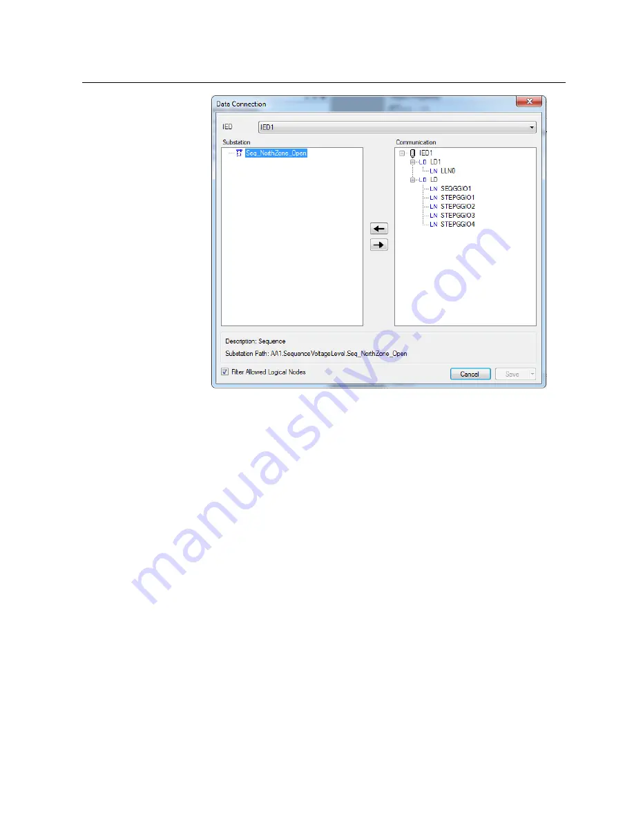
Figure 5.2-2 Connecting sequence logical nodes to sequence bay

4.

Click Save.

Adding a sequence start/stop control

5.3.

To create a sequence SLD:
1.

Launch the SLD Editor for the sequence bay object by right-clicking it in the Sub-
station structure and selecting SLD Editor.

43

COM600 series 5.1

1MRS755001

Sequence Control Configuration Manual

Содержание COM600 series

Страница 1: ...COM600 series 5 1 Sequence Control Configuration Manual...

Страница 2: ......

Страница 3: ...Editor 19 4 2 Adding a new Sequence POU object 20 4 3 Creating a global variable list 22 4 4 Adding symbol configuration 23 4 5 Adding a new sequence start and end action 24 4 6 Adding an initial sequ...

Страница 4: ...5 Adding a button for sequence execution on step error 54 5 6 Adding a button for viewing sequence status 57 5 7 Updating COM600 runtime environment 59 6 Executing a sequence 60 6 1 Executing a seque...

Страница 5: ...be the sole responsibility of the person or entity applying the equipment and those so responsible are hereby requested to ensure that all measures are taken to exclude or mitigate such risks This pro...

Страница 6: ...1 5 This user s manual provides thorough information on the sequence control feature for COM600 Information in this user s manual is intended for application engineers who configure the sequence cont...

Страница 7: ...ing caution and information icons that point out safety related conditions or other important information It also includes tip icons to point out useful information to the reader The corresponding ico...

Страница 8: ...r an OPC internal value Normally an event consists of value quality and timestamp Event A physical IEC 61850 device that behaves as its own commu nication node in the IEC 61850 protocol Intelligent El...

Страница 9: ...Center NCC Object Linking and Embedding OLE OLE for Process Control OPC Protection Control P C Programmable Logic Controller PLC Program Organization Unit POU Request To Send RTS Substation Automatio...

Страница 10: ...uct revision Document version date Document created 4 0 A 31 5 2012 Document revised 4 1 B 13 3 2015 Document revised 5 0 C 24 5 2017 Document revised 5 1 D 22 3 2018 10 1MRS755001 COM600 series 5 1 S...

Страница 11: ...acilitate substation and grid automation solutions in IEC and ANSI market areas a variant based system similar to Relion 615 and 620 series is being followed from COM600 5 0 release The main reasons f...

Страница 12: ...re features of the COM600 series Overview of sequence control 2 3 The sequence control feature allows you to create sequences in the Logic Processor environment using the sequence control library and...

Страница 13: ...0 Configuring sequence control involves the following steps defining a sequence logical device and associated logical nodes for the logic processor IED defining a sequence SFC program in the logic pro...

Страница 14: ...ion structure in SAB600 with IEDs Adding a Logic Processor IED 3 2 To add a Logic Processor IED to the communication structure 1 Right click the Gateway object and select New Logic Processor OPC Serve...

Страница 15: ...ic Processor OPC Server object and add Logic Processor Sub network SAB600_SC_PLC_Subnetwork png Figure 3 2 2 Adding Logic Processor Subnetwork object 3 Right click the Logic Processor Subnetwork objec...

Страница 16: ...uence Logical Device 1 Right click the Logic Processor IED and select New Communication Sequence see Figure 3 3 1 SAB600_SC_PLC_LD png Figure 3 3 1 Adding a Sequence Logical Device object to the Logic...

Страница 17: ...data object for a STEPGGIO logical node Additional STEPGGIO logical nodes should be added for a sequence with multiple steps Table 3 4 1 Predefined logical nodes and data objects for a sequence logic...

Страница 18: ...nd associated data objects as defined in Table 3 4 1 An example of a finished configuration for a four step sequence after all the logical nodes and associated data objects have been defined is shown...

Страница 19: ...ext programming language The sequence should be implemented as a standard PLC Sequence Flow Chat SFC program within the logic processor environment To launch the Logic Editor right click the Logic Pro...

Страница 20: ...a new sequence POU object 1 Right click the Application object and select POU 2 In the Add POU dialog define a name for the intended sequence and set Sequential Function Chart SFC as the implementatio...

Страница 21: ...ditor_with_POU png Figure 4 2 1 Logic Editor view after adding a Sequence POU To modify a sequence POU 1 Right click a sequence POU and select Properties 2 In the Properties dialog go to the SFC Setti...

Страница 22: ...hanges Creating a global variable list 4 3 Create a global variable list for the Application object in the CoDeSys project if not already available To create a global variable list 1 Right click the A...

Страница 23: ...a sequence Each sequence intended within the logic processor should have a corresponding sequence object defined Array of SwitchObjects Variables allowing the logic processor runtime to control the sw...

Страница 24: ...d action 4 5 To add a new sequence start action 1 Right click the added POU object in the Devices view and select Add Object Action 2 Name the action as Start Set Structured Text ST as the implementat...

Страница 25: ...r define the sequence start action see Figure 4 5 2 sequence_start png Figure 4 5 2 Sequence start action definition 5 Right click the added POU object in the Devices view and add a new action by sele...

Страница 26: ...quence PRG 7 Select the added End action from the Devices view In the corresponding program editor define the sequence end action see Figure 4 5 4 sequence_end png Figure 4 5 4 Sequence end action def...

Страница 27: ...ial_Transition definition see Figure 4 6 1 adding_initial_transition png Figure 4 6 1 Defining initial transition for a sequence Adding a new action object 4 7 To add a new action object 1 Right click...

Страница 28: ...ence Adding a new transition object 4 8 To add a new transition object 1 Right click the added POU object in the Devices view and add a new transition by selecting Add Object Transition 28 1MRS755001...

Страница 29: ...lowing exceptions When adding an action object make sure that the program statement in the program editor corresponds to the action step number For example for a Step2_Action object the program statem...

Страница 30: ...added sequence steps 4 9 Editing start sequence 4 9 1 To edit the start sequence 1 Double click the added POU in the Device view to launch the program editor for the PLC Program The default view for...

Страница 31: ...ct the init step in the program editor and in the properties view Rename the Name parameter to Start_Sequence see Figure 4 9 1 2 Logic_Editor_Add_Start_Sequence png Figure 4 9 1 2 Adding Start_Sequenc...

Страница 32: ...k the button to launch the Input Assistant dialog 3 In the Input Assistant dialog click Subobjects in the Categories list 4 Select the Start action object and click OK This assigns the Start action ob...

Страница 33: ...nt png Figure 4 9 3 1 Launching the input assistant dialog to select Initial_Transition object 2 Assign the Initial_Transition object as the transition condition for the Start_Sequence step 3 Insert a...

Страница 34: ...gn an end action object to the sequence 1 Select Step0 and change the Name parameter to End_Sequence in the properties view see Figure 4 9 4 1 2 Assign the End action object to the End_Sequence step b...

Страница 35: ...select Insert step transition after to add step 1 in Sequence SFC 3 Rename the added step to Step 1 by editing the Name parameter in the properties view Also assign a Step1_Action action object for t...

Страница 36: ...iguration 4 10 After a successful build add the sequence POU to PLC MainTask configuration To add the sequence POU to PLC MainTask configuration 1 Double click MainTask in the Devices view In the Main...

Страница 37: ...nder Miscellaneous in the Add Library dialog 6 Exit Logic Editor and open SAB600 before proceeding to the next configuration steps Configuring sequence cross references 4 11 This section describes the...

Страница 38: ...m the Logic Processor select the data object from the communication structure view and drag and drop it to the corresponding sequence variable to be mapped 4 Edit the data object manually to map the r...

Страница 39: ...ogical device SEQGGIO1 Str data object and assign the needed logic processor variables to it Select the Control OPC Item Path parameter in the Object Properties view and click the button to launch the...

Страница 40: ...ta object and assign the needed logic processor variable to it Select the Control OPC Item Path parameter in the Object Properties view and assign it to SequenceObject SeqExecutionOnStepError variable...

Страница 41: ...for sequence control 1 In SAB600 right click the Substation object in the Substation Structure and select New Functional Sequences to add a sequence voltage level to the Substation structure see Figur...

Страница 42: ...Data Con nection dialog SAB600_SC_Launch_Data_Connection png Figure 5 2 1 Launching data connection dialog for the bay object 2 In the Data Connection dialog select Logic_Processor_IED from the IED dr...

Страница 43: ...ence bay 4 Click Save Adding a sequence start stop control 5 3 To create a sequence SLD 1 Launch the SLD Editor for the sequence bay object by right clicking it in the Sub station structure and select...

Страница 44: ...drop a 2 State Indicator button and a Multiple State Button from the Generic section in the Symbols dialog to the SLD layout page The 2 State Indic ator button control is required for starting and st...

Страница 45: ...te Indicator Button Configuration dialog see Fig ure 5 3 2 2_state_control png Figure 5 3 2 Adding a two state indicator button to sequence SLD for sequence open close control 4 Configure the Indicati...

Страница 46: ...Figure 5 3 3 Configuring a 2 State button with indication value 5 Click Add Command to add the Command tab Configure the Command properties as shown in Figure 5 3 4 46 1MRS755001 COM600 series 5 1 Seq...

Страница 47: ...5 3 4 Configuring a 2 State button for control command 6 In the Object Properties window set the corresponding property values for the added start stop control see Figure 5 3 5 47 COM600 series 5 1 1...

Страница 48: ...execution auto matic manual for the sequence To add an execution mode control 1 Drag and drop the 2 State Indicator Button control from the Generic section in the Symbols dialog to the SLD layout pag...

Страница 49: ...ring the Indication tab properties for a sequence execution mode 2 State Indicator Button 4 Click Add Command to add the Command tab Configure the Command properties as shown in Figure 5 3 4 49 COM600...

Страница 50: ...ommand tab properties for a sequence execution mode 2 State Indicator Button 5 In the Object Properties window set the corresponding property values for the added start stop control see Figure 5 3 5 5...

Страница 51: ...sequence execution mode 2 State Indicator Button Similarly add a new 2 State Indicator Button for acknowledging the sequence in manual mode 1 Configure the Indication properties as shown in Figure 5...

Страница 52: ...Indication tab properties for a sequence manual mode acknowledgement 2 State Indicator Button 2 Click Add Command to add the Command tab Configure the Command properties as shown in Figure 5 4 5 52 1...

Страница 53: ...b properties for a sequence manual mode acknowledgement 2 State Indicator Button 3 In the Object Properties window set the corresponding property values for the added start stop control see Figure 5 4...

Страница 54: ...rror setting To add a button for executing a sequence on step error 1 Drag and drop the 2 State Indicator Button control from the Generic section in the Symbols dialog to the SLD layout page 2 Right c...

Страница 55: ...ndication tab properties for a sequence execution on step error 2 State Indicator Button 4 Click Add Command to add the Command tab Configure the Command properties as shown in Figure 5 3 4 55 COM600...

Страница 56: ...properties for a sequence execution on step error 2 State Indicator Button 5 In the Object Properties window set the corresponding property values for the added start stop control see Figure 5 3 5 56...

Страница 57: ...ate Button control from the Generic section in the Symbols dialog to the SLD layout page 2 Right click the Multiple State Button and select Configure Multiple State Button to launch the configuration...

Страница 58: ...tate Button object properties for a sequence status 5 Repeat the steps to add the status for individual steps in the sequence Select the appropriate data attribute path when configuring the indication...

Страница 59: ...sure that SAB600 is configured to update the correct COM600 runtime To update the COM600 runtime environment 1 Right click the Gateway object in the Communication view and select Management 2 Click U...

Страница 60: ...ution mode Use this button to change the execution mode of the sequence between automatic and manual Manual mode acknowledge Use this button to manually acknowledge each step when the sequence is run...

Страница 61: ...As each step is executed the corresponding breaker switch mapped for the step is controlled to the desired state An example of a four step sequence in automatic execution mode is shown in Figure 6 2...

Страница 62: ...stop the sequence by double clicking the Start Stop object In the follow ing dialog click Stop Notice that as each step is executed the corresponding breaker switch mapped for the step is controlled...

Страница 63: ...37 data connection 42 data object 17 Logic Processor IED 14 logical node 17 overview 13 Sequence Logical Device 16 WebHMI 41 D data object 17 assigning item paths 39 E executing sequence 60 automatic...

Страница 64: ...24 initial transition 27 POU 20 22 start action 24 symbol configuration 23 transition 28 Sequence Logical Device 16 sequence SLD 2 State Indicator Button 43 execution mode control 48 manual mode 51 on...

Страница 65: ......

Страница 66: ...Phone 358 10 22 11 ABB Distribution Automation 4300 Coral Ridge Drive Coral Springs Florida 33065 Phone 1 954 752 6700 www abb com mediumvoltage www abb com substationautomation 1MRS755001 D 22 3 2018...

Отзывы: