Control
IT
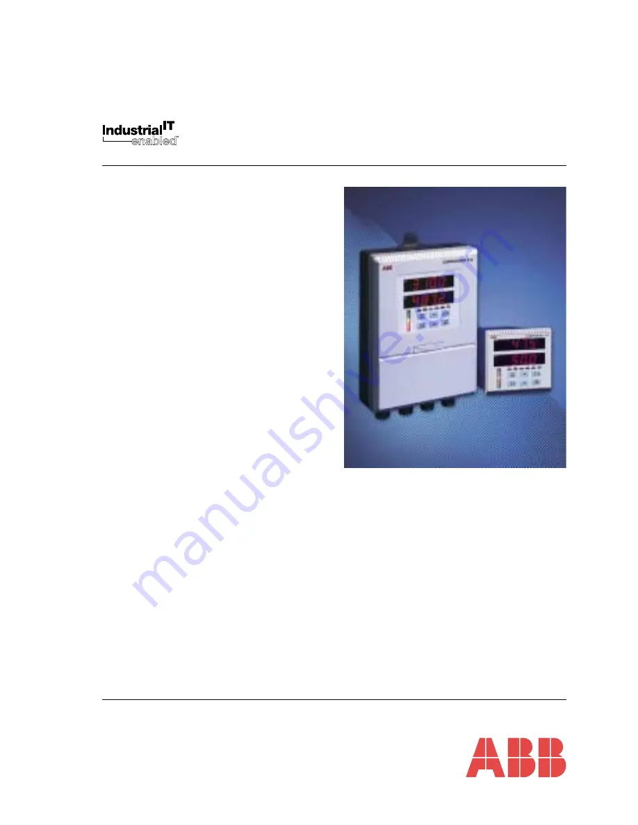
Universal Process Controllers
C300 and C310
Operating Guide
IM/C300–OG_7
Страница 1: ...ControlIT Universal Process Controllers C300 and C310 Operating Guide IM C300 OG_7 ...
Страница 2: ...utions must be taken to avoid the possibility of an accident occurring when operating in conditions of high pressure and or temperature 5 Chemicals must be stored away from heat protected from temperature extremes and powders kept dry Normal safe handling procedures must be used 6 When disposing of chemicals ensure that no two chemicals are mixed Safety advice concerning the use of the equipment d...
Страница 3: ...otorized Valve Control 9 5 2 3 Heat Cool Control 10 5 3 Operating Page Messages 11 5 4 Alarm Acknowledge Page 13 5 4 1 Mode Alarm Trips 13 5 5 Access to Configuration Levels 14 5 5 1 Security Code Page 14 6 TUNING LEVEL 15 6 1 Introduction to Self tuning 15 6 2 Self tuning Page 16 6 3 Self tune Diagnostic Messages 20 7 CONTROL LEVEL 21 7 1 Introduction to Standard Control 21 7 2 Control Page 23 7 ...
Страница 4: ...AMMING Part No IM C300 PG Basic Config Level Advanced Config Level OPERATION Setting Up Displays Controls Operating Level Simple Fault Finding Part No IM C300 OG Part No IM C300 INS or IM C310 INS INSTALLATION Product Identification Siting Mounting Electrical Connections Installation Record MODBUS RTU Serial Adaptors Serial Connections Programming Page Part No IM C300 MOD or IM C310 MOD SPECIFICAT...
Страница 5: ...ument Is there a signal at the process variable input and or the control output terminals Line Failed indicates power has been restored after a failure Cleared by pressing the switch Instrument Test identifies the instrument type C300 C301 or C310 see Table 2 1 in the Installation Guide or C300 tESt Configuration Check indicates configuration error Acknowledged by pressing the switch C310 tESt LIN...
Страница 6: ...shing alarm active but not acknowledged LED On all active alarms acknowledged LED Off alarms inactive L On if the local set point is being used see Section 4 2 in Programming Guide R On if the remote set point is being used see Section 4 2 in Programming Guide Both L and R off if dual set point or dual fixed set points are used see Section 4 2 in Programming Guide ST On while the self tune procedu...
Страница 7: ...lecting Automatic or Manual mode on alternate operations When Manual mode is selected the displays revert automatically to the process variable values and control output or valve position if position proportioning or boundless motorized valve control is selected at Control Type frame in the Set Up Control Page See Section 4 10 in the Programming Guide Fig 3 6 Auto Manual Switch Functions Frame 1 F...
Страница 8: ...ection 8 1 Page 29 Self tuning Page Section 6 2 Page 16 Control Page Section 7 2 Page 23 Profile States Page Section 8 2 Page 30 Set Point Page hidden if Profile Function is OFF Page hidden if Profile Function is ON or Boundless control is selected Incorrect Security Code Correct Security Code Information The instrument has dedicated Operating Pages These pages are used for general monitoring of t...
Страница 9: ...same value as the process variable Without set point tracking enabled the response following a manual to auto transfer depends on the control settings With an integral action setting the output is ramped up or down to remove any process variable offset from the set point providing the process variable is within the proportional band If the integral action is off the output may step to a new value ...
Страница 10: ... the switch to view the various set point values If the difference is too great press the switch and return to the Control Set Point frame and adjust the Local set point to obtain an acceptable difference The Local set point tracks the Remote set point when the Remote set point is selected providing Remote Set Point Tracking Enable is set to YES see Section 4 2 of the Programming Guide Set Points ...
Страница 11: ...ntegral Action Time is set or Manual Reset Adjust Enable is set to OFF see Section 7 2 Control Page Use the and switches to set a value which eliminates any offset from the set point Temperature Units This frame is not displayed if the Display Units parameter is set to NONE see Section 4 8 of the Programming Guide Set Up Display Page Set Point Type Selection Fig 5 1 previous page Use the switch to...
Страница 12: ...ut is above the Crossover Value Heat Output This frame is not displayed if the P I D output is below the Crossover Value PID Output 100 3 110 5 100 3 OP 50 0 100 3 oh 50 0 100 3 oc 50 0 100 3 rc 50 0 100 3 rh 50 0 100 3 dEG F rAtIO 1 000 bIAS 0 0 LOCAL 110 5 Manual Reset Heat and Cool 0 to 100 This frame is not displayed if an Integral Action Time is set or Manual Reset Adjust Enable is set to OFF...
Страница 13: ...n lower display when position feedback exceeds its fault detection level Failed Linearizer Range flashes in upper display when lineariser range set exceeds that allowed for the input linearizer selected High Process Alarm flashes when a high process alarm condition is present and unacknowledged Low Process Alarm flashes when a low process alarm condition is present and unacknowledged High Deviatio...
Страница 14: ...arm flashes when a fast rate alarm condition is present and unacknowledged Slow Rate Alarm flashes when a slow rate alarm condition is present and unacknowledged Mode Alarm flashes when a mode alarm condition is present and unacknowledged Program Event Alarm flashes when a program event alarm condition is present and unacknowledged Segment Event Alarm flashes when a segment event alarm LOUt HOUt F...
Страница 15: ...m is acknowledged pressed ACKNGd is displayed Rate of change alarms have trip levels expressed in of span per hour Return to top of page or advance to Security Code Page or Profile Operating Page 5 4 Alarm Acknowledge Page Table 5 2 Alarm Types Mode Trip Values 5 4 1 Mode Alarm Trips ACKNLG ALArMS SECOdE 0 P StAt or A HPrC 100 5 ACKNGd A HPrC Message Description In Automatic Control Mode In Manual...
Страница 16: ...gramming Guide 5 5 1 Security Code Page Page Header Security Code Page Set the security code to the correct Tune or Configuration password using the and switches and press the switch to enter the code The passwords are programmed in the Access Page Refer to Section 4 15 of the Programming Guide Software version The Upper display indicates the EPROM series 2201 is displayed for the standard C300 EP...
Страница 17: ...p tuning only can be selected Error and Caution messages indicate reason for tuning problems Self tune facility not available on Heat Cool Control and Boundless Fig 6 1 Start Up Self tuning Information The noise level of the process is monitored and then a step is applied to the control output value The response of the process is recorded and these results are used to calculate the control terms S...
Страница 18: ...t point and stable The control output must also be stable However for best results the Manual control mode can be used to stabilize the output and the process value The output must be adjusted slowly to allow process response to the change to bring the process variable to the required control set point The closer the process is to the set point the more effective the self tuning cycle 6 2 Self tun...
Страница 19: ...is reduced Maximum is 50 Example If the controller output value 30 and the selected step size 50 The step size is reduced to 30 The step size should be large enough so that the amplitude of the process variable excursions are at least four times larger than the hysteresis parameter to allow the best possible response data The output step size must be small enough to avoid the process variable cros...
Страница 20: ... A for quickest response with 1 4 wave damping or b for quickest response with minimum overshoot Self tune Mode Selection With the self tune mode enabled the ST l e d is illuminated while the controller calculates the control terms selected above On completion of the self tune sequence the ST l e d flashes Select ON to enable OFF to disable The time taken for completion of self tuning is dependent...
Страница 21: ...lf tune process a To view alternative control combinations return to the Control terms and Control type if applicable frames and set to the required alternative settings b Set the Self tune Mode to ON It reverts automatically to OFF to indicate that the new advisory values have been calculated c View the re calculated advisory values Select YES to accept the advisory values The values automaticall...
Страница 22: ...sis must be at least equal to and preferably greater than process noise If possible use a larger output step value Check input wiring to find the cause of the failure or restart self tuning with a smaller output step size The process variable signal is excessively noisy Check input wiring to try and find the source of the problem If the process is changing rapidly then allow it to settle before re...
Страница 23: ...enable faster approach to the set point by enabling use of a smaller proportional band to minimize overshoot 7 CONTROL LEVEL Fig 7 1 Manual Tuning Increase Proportional Band P I D P 2 x PBc P I 2 2 x PBc tc 1 2 P D 1 6 x PBc tc 2 tc 12 Time Process Variable Response Time Time Process Variable Response Time Process Variable Response Time Critical Cycle time tcc Decrease Proportional Band Calculate ...
Страница 24: ...ble Longer period Larger oofset Stability decreases High Prop Band Low Prop Band Derivative Increases stability permitting smaller proportional band and larger integral action times to be used Reduces height of first peak Reduces period of oscillation Stability decreases Process noise is amplified M a x i m u m contribution not realized Derivative Action Time too High Derivative Action Time Correc...
Страница 25: ...ycle time between 1 0 and 300 in 0 1 second increments or if ON OFF mode is required select cycle time below 1 0 second Hysteresis This frame appears only if ON OFF is selected in Cycle Time The output turns off at the set point value but does not turn on again until it has moved into the safe region by an amount equal to the hysteresis value This is only applicable to ON OFF control Set the requi...
Страница 26: ...ce of 7201 120 1 Note An Integral Action Time must be set when the Control Type is set to bNdLSS Manual Reset Manual reset is only operable with Integral Action Time set to OFF Set the required proportional band offset between 0 0 and 100 0 of the display engineering span in 0 1 increments Derivative Action Time Set the required time between 0 0 and 999 9 in 0 1 second increments 0 1 and 16 67 min...
Страница 27: ...jority of applications the heat and cool outputs have opposing control actions i e one is direct acting and the other is reverse In this configuration both outputs are at 0 within the off hysteresis band The band setting is used to prevent oscillation of control changes Heat Cool Outputs refer to P I D Output above Note Refer to Sections 7 3 2 and 7 3 3 for Crossover Value and Transition Bandwidth...
Страница 28: ...ed between 0 1 and 999 9 in 0 1 increments Time Units The time units for the integral and derivative action times see below can be set to minutes MINS or seconds SECS Integral Action Time Heat Set the required time between 1 and 7200 in 1 second increments 0 1 and 120 minutes in 0 1 minute increments OFF is displayed in place of 7201 120 1 Manual Reset Heat This is only operable with Integral Acti...
Страница 29: ... initially Manual Reset Adjust Enable Manual Reset display and adjustment in the Operating Page see Section 5 2 can be enabled or disabled Select YES to enable or no to disable Crossover Output Value Set the required crossover output value between 0 0 and 100 0 of P I D output in 0 1 increments see Section 7 3 2 Transition Bandwidth Set the required value between 0 0 and 100 0 of P I D output in 0...
Страница 30: ...imum of 1 5kW and absorb 0 75kW Output Gain Ratio 1 5 0 75 2 Crossover Value 100 2 1 33 3 7 3 3 Calculating the Transition Bandwidth Value Fig 7 3 The Transition Bandwidth is the percentage difference of the proportional band settings Example if the proportional band settings for the heat output is 20 and for the cool output is 25 Transition Bandwidth 25 20 25 x 100 Transition Bandwidth 20 If the ...
Страница 31: ...an external switch is complete and the switch is still in the Start Profile position Countdown Time This is only accessed if a Time Delay for the profile start has been set in the Profile States Page see next page The countdown time remaining is displayed in minutes Return to top of the Profile Operating Page Current Program and Segment The current program and segment number is shown The program o...
Страница 32: ...elect 7 press the switch Select 3 press the switch If less than four programs are required end by selecting and storing the terminator W Select a program or the terminator W Press the switch to advance to the next program in the running order character flashing or if the selection is complete advance to the next parameter Time Delay A countdown time may be set to provide a controlled delay before ...
Страница 33: ...e This frame is omitted if a logic input has been assigned to the Profile Reset function i e P rSEt has been selected see Section 4 10 of the Programming Guide no is displayed on entry to this parameter When the switch is pressed to reset the profile the display changes to YES then reverts to no If the profile is reset and a hold condition does not exist see next parameter the profile returns to t...
Страница 34: ...itch is pressed the profile immediately abandons the current segment and executes the next segment Normally the Current Segment number is displayed on the lower display C dn is displayed during a countdown time see Time Delay which can also be skipped if required If the segment being skipped is the last segment then ENd is displayed Press the switch to skip the next segment Return to top of Profil...
Страница 35: ...rumentation pH conductivity and dissolved oxygen transmitters and sensors ammonia nitrate phosphate silica sodium chloride fluoride dissolved oxygen and hydrazine analyzers Zirconia oxygen analyzers katharometers hydrogen purity and purge gas monitors thermal conductivity Customer Support We provide a comprehensive after sales service via a Worldwide Service Organization Contact one of the followi...
Страница 36: ...tained herein without notice Printed in UK 06 04 ABB 2004 ABB Inc 125 E County Line Road Warminster PA 18974 USA Tel 1 215 674 6000 Fax 1 215 674 7183 ABB Limited Howard Road St Neots Cambridgeshire PE19 8EU UK Tel 44 0 1480 475321 Fax 44 0 1480 217948 ABB has Sales Customer Support expertise in over 100 countries worldwide www abb com ...