


16
12345678
9
Kathar
ometers
10
11
12
13
12345678
9
1
0
1
1
1
2
1
3
23
24
25
26
14
15
16
17
18
19
20
21
22
L N E E
Mains T/B
6553 Outputs
Upper Display
6553 Outputs
Lower Display
N/O
Common
N/C
N/O
Common
N/C
N/O
Common
N/C
N/O
Common
N/C
Common
Range 3
Range 2
Range 1
Cubicle T
erminal Blocks
+
–
+
–
H
2
in Air
Alarm 1
H
2
in Air
Alarm 2
H
2
in Air
Alarm 1
H
2
in Air
Alarm 2
Retransmission
Retransmission
Range Selector
Switch Position
Indicator
Range Selector
Switch Position
Indicator
2
3
91
0
14
Kathar
ometer
Panel 1
2
3
91
0
14
Kathar
ometer
Panel 2
Hazar
dous Ar
ea
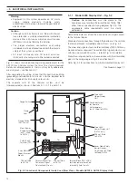
Note. I.S. Cir
cuits
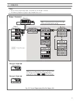
It is imperative that wiring instructions ar
e followed implicitly
.
Earth continuity must be checked for corr
ect bonding.
Note.
Kathar
ometer Panel 1 is connected inter
nally to the Upper Display of the 6553 Display/Contr
ol Unit.
Kathar
ometer Panel 2 is connected inter
nally to the Lower Display of the 6553 Display/Contr
ol Unit.
14
15
16
17
18
19
20
21
22
23
24
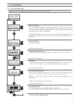
Optional
Low Flow
Alarms
Ex ia llC T4
Optional
Low Flow
Alarm Relays
2
3
1
42
3
1
4
L N E E
Common
N/C
N/O
Common
N/C
N/O
Relay 1
Relay 2 *
Te
rm
inal
Box
Screen
Black
Red
White
Screen
Black
Red
White
Kathar
ometer
H
2
& Air in CO
2
H
2
in Air
Kathar
ometer
H
2
& Air in CO
2
H
2
in Air
+
+
––
+
+
––
*
*
*
*
Note
. Not available if single Model AK103 is fitted to the cubicle.
Common
Range 3
Range 2
Range 1
Fig. 5.4 Wiring Diagram for Cubicle-Mounted Display/Contr
ol Unit
…5
ELECTRICAL INSTALLATION


