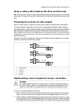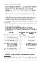
value (based on a motor thermal model) or an actual temperature indication given by motor
temperature sensors.
The motor thermal protection model supports thermal memory retention and speed sensitivity.
The user can tune the thermal model further by feeding in additional motor and load data.
The most common temperature sensors are:
•
motor sizes IEC180…225: thermal switch, for example Klixon
•
motor sizes IEC200…250 and larger: PTC or Pt100.
See the firmware manual for more information on the motor thermal protection.
■
Protecting the drive against ground faults
The drive is equipped with an internal ground fault protective function to protect the unit
against ground faults in the motor and motor cable. This function is not a personnel safety
or a fire protection feature. See the firmware manual for more information.
Residual current device compatibility
The drive is suitable to be used with residual current devices of Type B.
Note:
As standard, the drive contains capacitors connected between the main circuit and the
frame. These capacitors and long motor cables increase the ground leakage current and
may cause nuisance faults in circuit breakers.
■
Implementing the emergency stop function
You can order the drive with an emergency stop function.
See the appropriate manual for more information.
Code
Name
3AUA0000119895
Emergency stop, stop category 0 (Q951) for ACS880-07/17/17LC/37/37LC drives
user's manual
3AUA0000119896
Emergency stop, stop category 1 (Q952) for ACS880-07/17/17LC/37/37LC drives
user's manual
■
Implementing the Safe Torque Off function
See chapter
on page
■
Implementing the Power loss ride-through function
Implement the power-loss ride-through function as follows:
•
Check that the power-loss ride-through function of the drive is enabled with parameter
30.31
.
•
Set parameter
21.01
(in vector mode) or parameter
21.19
(in scalar mode) to make
flying start (starting into a rotating motor) possible. If the installation is equipped with a
main contactor, prevent its tripping at the input power break. For example, use a time
delay relay (hold) in the contactor control circuit.
WARNING!
Make sure that the flying restart of the motor will not cause any danger. If you are
in doubt, do not implement the Power-loss ride-through function.
Guidelines for planning the electrical installation 69
Содержание ACS880-37LC
Страница 1: ... ABB INDUSTRIAL DRIVES ACS880 37LC drives Hardware manual ...
Страница 2: ......
Страница 4: ......
Страница 78: ...78 ...
Страница 116: ...116 ...
Страница 134: ...5 Set the real time clock 134 Maintenance ...
Страница 144: ...144 ...
Страница 167: ... Dimension drawing examples ACS880 37LC 0390A 7 with main contactor Dimensions 167 ...
Страница 169: ...ACS880 37LC 1270A 7 with common motor terminal cubicle Dimensions 169 ...
Страница 170: ...ACS880 37LC 1940A 7 with common motor terminal cubicle 170 Dimensions ...
Страница 171: ...Cabinet height and depth Marine construction option C121 IP42 side view Non marine IP42 side view Dimensions 171 ...
Страница 172: ...Location and size of input terminals Contact ABB for details 172 Dimensions ...
Страница 174: ...Inverter module cubicle with two R8i modules bottom cable exit 174 Dimensions ...
Страница 175: ...Inverter module cubicle with three R8i modules bottom cable exit Dimensions 175 ...
Страница 176: ...Brake chopper cubicle D150 176 Dimensions ...
Страница 177: ... Units with common motor terminal cubicle H359 Cubicle width 300 mm bottom cable exit Dimensions 177 ...
Страница 178: ...Cubicle width 300 mm top cable exit 178 Dimensions ...
Страница 179: ...Cubicle width 400 mm bottom cable exit Dimensions 179 ...
Страница 180: ...Cubicle width 400 mm top cable exit 180 Dimensions ...
Страница 181: ...Cubicle width 600 mm bottom cable exit Dimensions 181 ...
Страница 182: ...Cubicle width 600 mm top cable exit 182 Dimensions ...
Страница 198: ...198 ...
Страница 200: ...200 ...


