


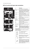


BCU-x2 control unit layout and connections
Description
I/O terminals (see following diagram)
I/O
I/O extension, encoder interface or fieldbus
adapter module connection. (This is the
sole location for an FDPI-02 diagnostics
and panel interface.)
SLOT 1
I/O extension, encoder interface or fieldbus
adapter module connection
SLOT 2
I/O extension, encoder interface, fieldbus
adapter or FSO-xx safety functions module
connection
SLOT 3
RDCO-0x DDCS communication option
module connection
SLOT 4
Memory unit connection
X205
Holder for real-time clock battery (BR2032)
BATTERY
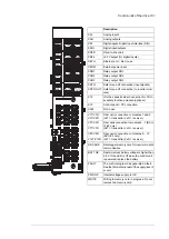
Mode selector for analog input AI1 (I =
current, U = voltage)
AI1
Mode selector for analog input AI2 (I =
current, U = voltage)
AI2
Termination switch for drive-to-drive link
(D2D)
D2D TERM
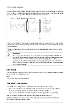
Ground selection. Determines whether
DICOM is separated from DIOGND (ie. the
common reference for the digital inputs
floats). See the ground isolation diagram.
DICOM=
DIOGND
7-segment display
Multicharacter indications are displayed as repeated se-
quences of characters
(“U” is indicated briefly before “o”.)
Control program running
Control program startup in progress
(Flashing) Firmware cannot be started.
Memory unit missing or corrupted
Firmware download from PC to control unit
in progress
At power-up, the display may show short
indications of eg. “1”, “2”, “b” or “U”. These
are normal indications immediately after
power-up. If the display ends up showing
any other value than those described, it in-
dicates a hardware failure.
100 Control units of the drive
Содержание ACS880-37LC
Страница 1: ... ABB INDUSTRIAL DRIVES ACS880 37LC drives Hardware manual ...
Страница 2: ......
Страница 4: ......
Страница 78: ...78 ...
Страница 116: ...116 ...
Страница 134: ...5 Set the real time clock 134 Maintenance ...
Страница 144: ...144 ...
Страница 167: ... Dimension drawing examples ACS880 37LC 0390A 7 with main contactor Dimensions 167 ...
Страница 169: ...ACS880 37LC 1270A 7 with common motor terminal cubicle Dimensions 169 ...
Страница 170: ...ACS880 37LC 1940A 7 with common motor terminal cubicle 170 Dimensions ...
Страница 171: ...Cabinet height and depth Marine construction option C121 IP42 side view Non marine IP42 side view Dimensions 171 ...
Страница 172: ...Location and size of input terminals Contact ABB for details 172 Dimensions ...
Страница 174: ...Inverter module cubicle with two R8i modules bottom cable exit 174 Dimensions ...
Страница 175: ...Inverter module cubicle with three R8i modules bottom cable exit Dimensions 175 ...
Страница 176: ...Brake chopper cubicle D150 176 Dimensions ...
Страница 177: ... Units with common motor terminal cubicle H359 Cubicle width 300 mm bottom cable exit Dimensions 177 ...
Страница 178: ...Cubicle width 300 mm top cable exit 178 Dimensions ...
Страница 179: ...Cubicle width 400 mm bottom cable exit Dimensions 179 ...
Страница 180: ...Cubicle width 400 mm top cable exit 180 Dimensions ...
Страница 181: ...Cubicle width 600 mm bottom cable exit Dimensions 181 ...
Страница 182: ...Cubicle width 600 mm top cable exit 182 Dimensions ...
Страница 198: ...198 ...
Страница 200: ...200 ...