


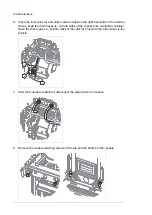


9.
Pull the module carefully out onto a table or other platform. Keep the module secured
to a hoist or equivalent to prevent the module from falling. For information on using the
lifting device, see
Converter module lifting device for drive cabinets hardware manual
(3AXD50000210268 [English]).
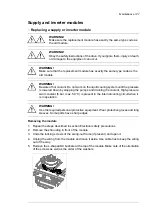
Reinstalling the module
1.
Push the module carefully into its bay.
2.
Fasten the retaining screws at the top and the bottom of the module.
3.
Reinstall the DC busbars at the top of the module.
4.
Reconnect the coolant pipes to the module.
5.
Reconnect the control wiring to the module.
6.
Fill up the cooling system. For instructions, see section
7.
Close the swing-out frame (if present). Reinstall all shrouds removed earlier.
8.
If the module is an inverter module, and the Safe torque off function is in use, perform
an acceptance test as described under
Start-up including acceptance test (page 191)
■
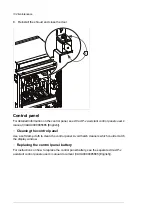
Cleaning the heatsink
The drive module heatsink fins pick up dust from the cooling air. The drive runs into
overtemperature warnings and faults if the heatsink is not clean. When necessary, clean
the heatsink as follows.
WARNING!
Obey the safety instructions of the drive. If you ignore them, injury or death, or
damage to the equipment can occur.
If you are not a qualified electrician, do not do installation or maintenance work.
WARNING!
Use a vacuum cleaner with antistatic hose and nozzle. Using a normal vacuum
cleaner creates static discharges which can damage circuit boards.
1.
Stop the drive and do the steps in section
Electrical safety precautions (page 17)
before
you start the work.
2.
Remove the drive module from the cabinet.
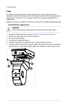
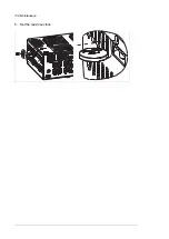
3.
Remove the module cooling fan(s). See the separate instructions.
4.
Blow dry, clean and oil-free compressed air from bottom to top and simultaneously use
a vacuum cleaner at the air outlet to trap the dust.
Note:
If there is a risk of dust entering adjoining equipment, perform the cleaning in another
room.
5.
Reinstall the cooling fan.
Capacitors
The DC circuit of the power modules of the drive contain several electrolytic capacitors.
Their lifespan depends on the operating time of the drive, loading and ambient temperature.
Capacitor life can be prolonged by lowering the ambient temperature.
Maintenance 129
Содержание ACS880-37LC
Страница 1: ... ABB INDUSTRIAL DRIVES ACS880 37LC drives Hardware manual ...
Страница 2: ......
Страница 4: ......
Страница 78: ...78 ...
Страница 116: ...116 ...
Страница 134: ...5 Set the real time clock 134 Maintenance ...
Страница 144: ...144 ...
Страница 167: ... Dimension drawing examples ACS880 37LC 0390A 7 with main contactor Dimensions 167 ...
Страница 169: ...ACS880 37LC 1270A 7 with common motor terminal cubicle Dimensions 169 ...
Страница 170: ...ACS880 37LC 1940A 7 with common motor terminal cubicle 170 Dimensions ...
Страница 171: ...Cabinet height and depth Marine construction option C121 IP42 side view Non marine IP42 side view Dimensions 171 ...
Страница 172: ...Location and size of input terminals Contact ABB for details 172 Dimensions ...
Страница 174: ...Inverter module cubicle with two R8i modules bottom cable exit 174 Dimensions ...
Страница 175: ...Inverter module cubicle with three R8i modules bottom cable exit Dimensions 175 ...
Страница 176: ...Brake chopper cubicle D150 176 Dimensions ...
Страница 177: ... Units with common motor terminal cubicle H359 Cubicle width 300 mm bottom cable exit Dimensions 177 ...
Страница 178: ...Cubicle width 300 mm top cable exit 178 Dimensions ...
Страница 179: ...Cubicle width 400 mm bottom cable exit Dimensions 179 ...
Страница 180: ...Cubicle width 400 mm top cable exit 180 Dimensions ...
Страница 181: ...Cubicle width 600 mm bottom cable exit Dimensions 181 ...
Страница 182: ...Cubicle width 600 mm top cable exit 182 Dimensions ...
Страница 198: ...198 ...
Страница 200: ...200 ...