12 Operation principle and hardware description
Operation basics
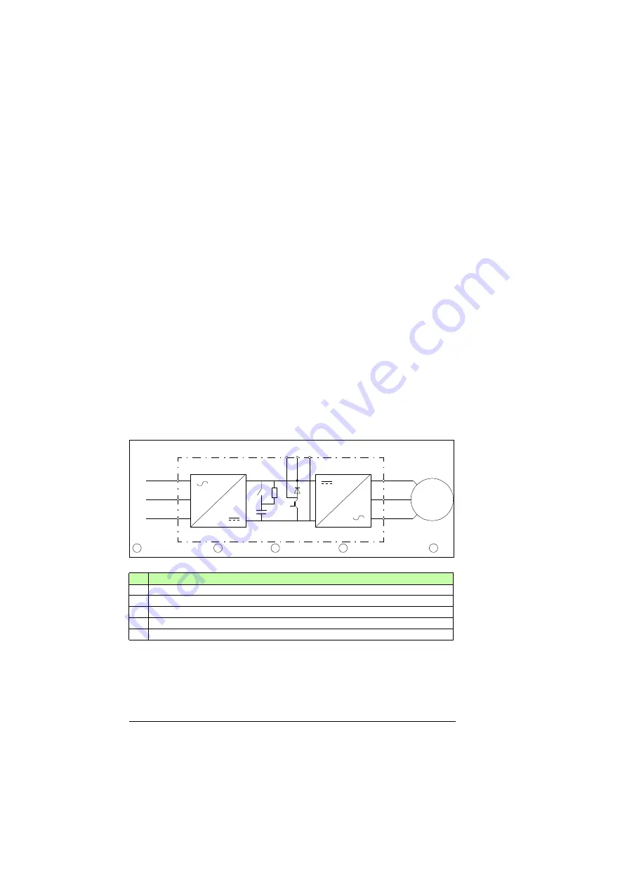
The main circuit of the drive consists of a rectifier, a DC link and an inverter. The rectifier
(input bridge) converts the alternating current and voltage to direct current and voltage for
the DC link. The DC capacitors in the DC link smooth the ripple and form a steady energy
and power supply for the inverter. The inverter converts the intermediate circuit DC power
to AC power for the motor.
From a common DC system point of view, the motor has two main operation modes: the
motoring mode and the generating mode. In the motoring mode, the motor rotates the
machinery. The energy flows from the AC power line to the motor through the rectifier, DC
link and the inverter. In the generating mode, the machinery rotates the motor. This is the
case for example when a hoist motor of a crane lowers a load (overhauling load). To keep
the rotation speed steady, the motor brakes. During the braking, the motor generates
energy back to the inverter which then conveys the energy further to the DC link.
In the generating mode the DC capacitors are charged by the inverters and the DC link
voltage starts to rise. To prevent an excessive voltage rise, the drive must convey the
surplus energy away from the DC link. There are three options: to convey the energy to
the AC power line, to a brake resistor or to another drive. For the first option you need to
have a special type of drive in use, a regenerative drive. If you have an ordinary drive with
a rectifier (diode input bridge), regeneration is not possible so only the two other options
remain. If you connect a brake chopper and resistor to the DC link, you can dissipate the
energy in the resistor as heat. If you connect the DC link of the drive to another drive, you
can use the surplus energy for charging the DC capacitors of the other drive and use the
energy to rotate its motor. This is a common DC system.
No.
Description
1.
AC power line
2.
Rectifier (input bridge)
3.
DC link including DC capacitors (a), its charging circuit (b) and brake chopper (c)
4.
Inverter
5.
Motor
L1
L2
L3
U
V
W
R-
UDC+
R+
UDC-
M
~3
~3
1
2
3
4
5
a
b
c
Содержание ACS880-04 drive modules
Страница 1: ...ABB industrial drives Application guide ACS880 01 drives and ACS880 04 drive modules Common DC systems...
Страница 4: ......
Страница 10: ...10 Introduction to the manual...
Страница 16: ...16 Operation principle and hardware description...
Страница 30: ...30 Planning basics...
Страница 38: ...38 Planning additional instructions...
Страница 48: ...Contact us www abb com drives www abb com drivespartners 3AUA0000127818 Rev B EN 2014 04 17...


