


Chapter 5 – Standard Application Macro Programs
ACH 500 Programming Manual
5-3
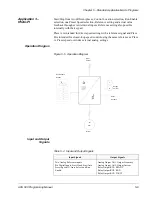
Application 1 –
HVAC
All drive commands, reference settings, and parameter settings can be
undertaken from the local keypad or through the screw terminals. Select the
control device with Parameter 9 (Control Location). Two analog and three
relay contact signals are available on Terminal Block X50.
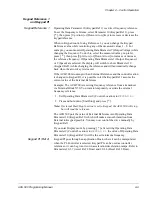
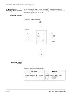
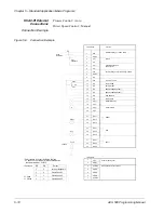
Operation Diagram
Figure 5-1 Operation Diagram
Input and Output
Signals
Table 5-2 Input and Output Signals
Input Signals
Output Signals
Two Analog Reference inputs.
Six Digital Inputs: Start Hand, Start Auto,
Preset Speed (2), Auto Select, and Run
Enable.
Analog Output AO1: Output Frequency
Analog Output AO2: Output Current
Relay Output RO1: READY
Relay Output RO2: RUN
Relay Output RO3: FAULT
f
A
M
3
Φ
Output
Current
Relay
Outputs
Motor
Ext. Controls
Input
Power
location


