
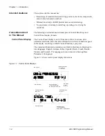


Chapter 3 – Start-up Data
ACH 500 Programming Manual
3-3
F MOTOR CURRENT
-FLA
This parameter matches the ACH 500 to the rated motor current, adjustable
between 0 and 1000 amps. The drive uses this parameter for motor overload
protection and current (amperage) information displays.
If the accuracy of the current display (parameter O.3) is off by more than 10%
due to long motor cables (ACS 501 units only), a software calculation can be
installed by pressing and holding the [left arrow] until an exclamation point
appears on the display. This will calculate the current based on the motor
power and power factor. These parameters must be entered correctly for the
calculation to be accurate.
G MOTOR POWER
This parameter matches the motor rated power, adjustable between 0.7 hp and
1340 hp. The drive uses this parameter for motor overload and kWh
information displays. The left key switches the display between hp and kWh.
To change the display, press and hold the left key for two seconds.
H MOTOR POWER
FACTOR
This parameter matches the motor power factor (at rated speed and load on
sinusoidal power), adjustable between 0.10 and 1.0. The drive uses this
parameter for motor torque and power information displays.
I MOTOR BASE
FREQUENCY
This parameter is used to set the designed frequency of the motor, adjustable
from 30 Hz to 500 Hz in 10 Hz increments. Changing this value will
automatically set the Field Weakening Point (FWP) to the same value.
J MOTOR BASE R.P.M.
This parameter is used to set the nameplate speed of the motor and is
adjustable from 200 to the maximum 2 pole motor speed based on Start-up
Data Parameter I (Motor Base Frequency).
K MOTOR NOM.
VOLTAGE
This parameter is used to set the motor nameplate voltage. The default is
460 V for 480-volt units and 230 V for 230-volt units. Changing this
parameter automatically changes the Maximum Output Voltage.
Note: If the motor rated voltage is lower than the supply voltage, make sure
that the motor insulation is rated for the DC bus voltage level which is
V
IN
×
110%
×
1.35
×
1.3 minimum (input voltage
×
±
10% tolerance
×
peak of rectified wave
×
overvoltage limit).