


Chapter 6 – Parameters
6-36
ACH 500 Programming Manual
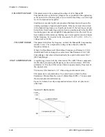
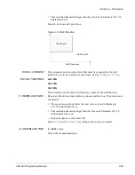
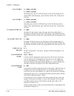
Figure 6-15 shows underload protection.
Figure 6-15 Underload Protection
13 UNDERLOAD CURVE
This parameter provides you with five selectable curves.
Torque limit for underload logic.
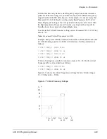
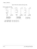
Figure 6-16 shows five available Underload Curve types. If the load drops
below the set curve for a longer time than the time set by Parameter 30.1.12,
the underload protection will activate. Curves 1 – 3 reach maximum at the
Field Weakening Point set by Parameter 20.4.4 (Field Weak Point).
Figure 6-16 Underload Curve Types
Underload Curve
T
M
5Hz
ƒ
Underload Region
ƒ
% of
100
80
60
40
20
0
120 Hz
ƒ [Hz]
3
2
1
5
4
Motor
Torque
70%
50%
30%
FWP