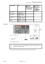
Fig. 2: Wiring of training case
For the example projects, not all input switches and none of the potentiometers
included in training case are necessary.
You will need switch I1 for the example project for central I/O expansion.
You will need switch I5 for the example project for remote I/O expansion.
1.4.2 System assembly, construction and connection
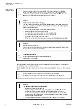
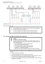
NOTICE!
Avoidance of electrostatic charging
PLC devices and equipment are sensitive to electrostatic discharge, which can
cause internal damage and affect normal operation. Observe the following rules
when handling the system:
–
Touch a grounded object to discharge potential static.
–
Wear an approved grounding wrist strap.
–
Do not touch connectors or pins on component boards.
–
Do not touch circuit components inside the equipment.
–
If available, use a static-safe workstation.
–
When not in use, store the equipment in appropriate static-safe packaging.
You can mount AC500 PLC either to DIN rail or to a metal plate. Here, we recommend to mount
on DIN rail.
1.
Snap the terminal base onto DIN rail.
2.
Snap the additional terminal units for I/O modules onto DIN rail.
3.
Make the sensor/actuator wire connections according to the dedicated electronic module
you want to use. Provide external process power supply as required.
4.
If required, make the fieldbus connections according to the dedicated master communica-
tion module you want to use.
Getting started with example projects
Hardware AC500 V2 > System assembly, construction and connection
2023/03/03
3ADR010649, 3, en_US
12


