


5
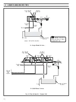
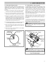
Sample Outlets
to Monitor
Stream Selection
Valves
Sample Inlet Tubes –
Streams 1, 2 and 3 respectively
Clean Drain
Tubes
Stream Selection
Valves
Out of Sample
Float Switches
Constant Head
Assembly
Sample Outlet to Monitor
Sample Inlet Tubes –
Streams 4, 5 and 6 respectively
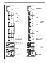
A – Single Stream Connections
B – Configuration of Multi-Stream Constant Head Units
Feed the reagent tubes through the
grommet, at the left hand rear corner
of the case, from beneath. Fit them
to the appropriate connectors (red to
red, and so on).
Push the drain tube (9mm i.d.)
onto the external tube hose
connector.
Push the sample inlet tube (6mm i.d.)
onto the constant head sample inlet
tube hose connector (the smaller of the
two tube connectors).
Push the clean drain tube (9mm i.d.)
onto the constant head clean drain tube
hose connector (the larger of the two
tube connectors).
1
2
3
4
2
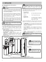
INSTALLATION…
Notes.
• Use tube of inert material, e.g., p.v.c.
• The sample inlet tube must incorporate a shut-off valve
at its up-stream end.
• Ensure the drain outlet tube is short, has a free fall and
is vented to atmosphere as soon as possible.
Fig. 2.2 External Pipe Connections
Information. To gain access to the constant head
assembly follow steps 1, 2, 4 and 5 in Fig. 1.1.
Note.
• One constant head assembly is fitted for each sample
inlet in multi-stream versions of the monitor.
• Fig. 2.2B shows six sample inlets and six
corresponding constant head assemblies.
2.5
Sample Connections – Fig. 2.2
Connect inlet and outlet tubes as shown in Fig. 2.2A (single
stream) and Fig. 2.2B (multi-stream).
Note. If the optional emergency sample facility has
been requested, a suitable 40 litre emergency sample
container must be provided by the user. A suggested
arrangement is shown in Fig. 4.2. Alternatively, a
constant, independent source may be used.


