


33
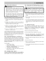
A – Location of Adjusting Screws
B – Setting the Lamp to Full intensity
Lamp
Mounting
Plate
Measuring
Photocell
Housing
Measuring
Cuvette
Lamp
Housing
Reference Photocell
Housing
Drain Pinch
Valve
Spring-loaded
Positioning Screws
Two Cuvette
Securing Screws
Adjust screws
to align optical
axis
Card
Power Supply
Unit (PSU)
Voltage
Adjustment
Potentiometer
8
MAINTENANCE…
8.6.2
Aligning the Exciter Lamp
a) To avoid spillages in the next step depress the pinch valve
plunger for two to three seconds to drain the cuvette.
b) Remove all tubing from the cuvette connectors.
c) Unscrew fully the two screws holding the cuvette in place
and remove the cuvette.
d) Scroll to Programming Page 2.2 and use the
switch to
select 'YES' for 'Switch lamp on continuous'.
e) Loosen off the three screws on the lamp mounting plate
until the light beam falls directly onto the photoelectric cell
window. Placing a piece of white card aids this adjustment
– see Fig. 8.4B.
f)
Fit the cuvette and the associated tubing.
Now set up the cuvette board – see Section 8.6.3.
8.6.3
Setting Up the Cuvette Board
a) Switch off the pump.
b) To avoid spillages in the next step depress the pinch valve
plunger for two to three seconds to drain the cuvette.
c) Remove the optical system cover if not already done so.
Remove the cuvette inlet tube from the cuvette connector.
This is a small diameter tube sited behind the drain tube.
d) Using a length of inlet tube from the spares kit connect a
syringe filled with demineralized water to the cuvette inlet
connector.
e) Slowly push the demineralized water through the cuvette
allowing it to overflow, and occasionally depressing the
pinch valve plunger.
Repeat this step once more before proceeding.
f)
Refill the syringe and fill the cuvette until it just overflows.
g) Now scroll to the Programming Page 6.2. (The security
code to enter Programming Page 6 is normally set to 42.)
The voltages at both the Read and Reference
photoelectric cells are displayed. The Reference voltage
remains constant at approximately 2 V whereas the Read
voltage will vary depending on the intensity of the color
complex formed with the phosphate in the sample. As
demineralized water is present in the cuvette, no color
exists and therefore represents a zero phosphate solution.
h) When the voltages are stable make fine adjustments with
the potentiometer, which is sited towards the bottom of the
cuvette board (see Fig. 8.5) until the Read voltage is
between 20 to 50 mV less than the Reference voltage.
i)
Connect the cuvette tube to the cuvette inlet connector and
fit the optical system cover.
j)
Select 'NO' for 'Switch lamp on continuous' on
Programming Page 2.2 to turn the lamp off. Switch on the
pump.
k) Allow the instrument to settle down for one hour before
performing a baseline calibration.
Fig. 8.4 Lamp Adjustment
Fig. 8.5 Location of the Potentiometer
on the Cuvette Board


