


4
205.5
205.5
173.5
173.5
660
Dimensions in mm.
OUT O
F SER
VICE
ALAR
M 1
CAL
ALAR
M 2
HOLD
OUT O
F SAM
PLE
Pho
spha
te 82
42
108.5
62
600
540
120
opening
240
740
863 Ref
411
55
85
Bracket Keyholes
6.5 o.d.
16.0 o.d.
6.3mm o.d.
Fixing Holes
110
Clearance
for lock
M20 Cable
Gland Entry
43mm Centres
Lower
Mounting
Spacers
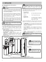
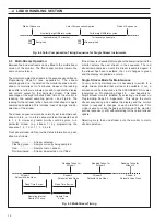
Mark the wall using the dimensions shown in
this figure.
Drill and plug the holes and screw in the top two
screws/bolts to leave a gap of 5mm between the
screw head and the wall.
Alternatively, with the enclosure carefully supported
against the wall, spot through using a suitable tool.
Hook the
enclosure onto
the Enclosure
Hanger Bracket
screws.
Spot through lower fixing holes from backplate.
Remove enclosure before drilling lower fixing holes.
347
1
2
3
2
INSTALLATION
Fig. 2.1 Mounting the Unit
Note.
• Mains (power supply) and
signal cables are connected
through cable glands directly
into the electronic section.
• Sample and drain pipe work
are brought in through the
bottom of the case.
2.1
Accessories
The accessories supplied are as follows:
1 x reagent container
2 x calibration solution containers
3 x solution container sealing caps
1 x spares kit
2.2
Location
Install in a clean, dry, well ventilated and vibration-free location
giving easy access, and where short sample lines can be
used. Avoid rooms containing corrosive gases or vapors, e.g.
chlorination equipment or chlorine gas cylinders. It is also
advisable to have adjacent drains near ground level, so that
the waste outlet from the monitor can be as short as possible,
together with maximum fall. Power supplies should also be
adjacent. Ambient temperature within the range 5
C to 40
C.
2.3
Mounting – Fig. 2.1
See Fig. 2.1 for mounting procedure.
2.4
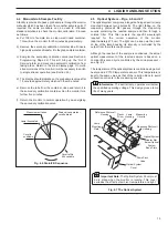
Sampling Requirements
In addition to being as close as possible to the monitor, the
sampling point must provide a thoroughly mixed
representative sample. The sample must also conform to the
following conditions:
a) Sample flowrates must be greater than 5 ml min
-1
.
b) Sample temperature should be within the range 5
C to 55
C.
c) Particles must be less than 10 mg l
-1
and the size must not
exceed 60 microns.
Note. To avoid erroneous readings and prevent
possible tube blockages the use of a sampling system
which provides the appropriate filtration of the sample is
recommended. ABB Ultrafiltration Units are the most
suitable for the purpose, details of which are available on
request. For power applications a 60 micron, in-line filter
should be used – part number: 0217 463.


