42 SBC347A 3U VPX Single Board Computer
Publication No. 500-9300527837-000 Rev. A.0
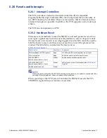
The following table shows the COM1 and COM2 routing to the VPX backplane
connectors:
COM1 and COM2 are connected using a single Intersil ISL 41334 transceiver,
which provides 15 kVolts ESD protection.
5.8.1 RS422/RS485 Mode
The mode of operation for COM1 and COM2 (i.e., RS232/RS422/RS485) can be
configured in the BIOS, by selecting the relevant option in the BIOS setup screen.
By default, this is set to RS232.
COM1 and COM2 support RS485 Auto Direction Control, which automatically
enables the RS485 transceiver when a character is ready to be transmitted.
Alternatively, when in RS422 mode, software must set the Ready to Send (RTS)
signal high by writing to the appropriate UART register, to enable the transceiver.
Again, this configuration is accessible in the BIOS set up screen.
CAUTION
Take care when connecting RS422/RS485 receivers to either COM port. The default mode of operation
is RS232 which could cause damage to an RS422/RS485 receiver because of its high operating
voltage. Ensure that the correct mode is set in the BIOS before connecting hardware.
Figure 5-3 RS422/RS485 Signal Definition
Table 5-6 COM1/COM2 Signal Availability
Port
RS232 Signal
RS422/RS485 Signal Pin
COM1
COM1_RXD
COM1_RXDA
P1/G11
COM1_TXD
COM1_TXDA
P1/G9
COM1_RTS~
COM1_RXDB
P2/G3
COM1_CTS~
COM1_TXDB
P2/G5
COM2
COM2_RXD
COM2_RXDA
P1/G15
COM2_TXD
COM2_TXDA
P1/G13
COM2_CTS
COM2_RXDB
P1/G7
COM2_RTS
COM2_TXDB
P1/G1


