


Publication No. HRMCR11 Rev. B.0
About This Manual 77
'+5 V
su
pplied by the CR! I and fused with max 2 A at C
TM
I 7 for normal
operation don't exceed 100 mA at thi
s
pi
n
.
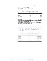
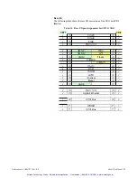
VGA2 Interface P4200
The optional second VGA monitor signal
s
are available on P4200 a 14-pin
male header
.
They are available if the front VGA option on the CR! I is not
mounted by order
(
i
.
e. when ordered with two PMC slots).
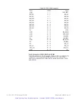
Table 46: VGA connector pin assignment
Name
V2_RED
V2_GREEN
V2_BLUE
V2_HSYNC
V2_VSYNC
GND
DOC-DATA
DDC-CLK
P4200
2
4
6
8
10
I, 3, 5, 7, 9, 11
12
13
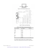
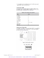
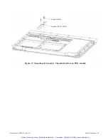
USB connector P1680
,
P1681
Four channels are available on a IO-pin wale header. USBVCC is supplied and
controlled by the CR! I board
.
It is fused with 2 A, but for normal operation
don't exceed 500 111.A at this cow1ectors .
•
• ••
s
••••••
••
•
••
••••
••
�
•
• ••••
••
•
• ••••
••
•
• ••••
••
• •
• ••••
•
f
• •
•
•
cD
• •
-
•
.
....
•
. ....
•
.....
cD
• • •
• • •
• •
•••••
•••••
• ••••
• ••••
• ••••
�
• • •
•
1 mma 1
• •
•
• ••••
.
....
• ••••
• ••••
• •
••••
• •
'
•••
.
••
•
•
• ••••
.....
•••••
• ••••
•••
t
•
Figure 33:
USB
connector location
vcc
USB- USB+ GND
\ I /
socket outside view
Artisan Technology Group - Quality Instrumentation ... Guaranteed | (888) 88-SOURCE | www.artisantg.com


