20 CR11*, CP11*, CT11* 6U CompactPCI® SBC
Publication No. HRMCR11 Rev. B.0
Dispose of used batteries according to instructions of Abaco Systems and
applicable local regulations
.
Installation of a plug-in board
Boards are installed in a CPCI c
h
assis by carefully sliding them into the guide
rails, inserting them all the way until the handles can be operated to seat and
lock the board in place
.
Handles typically have a lock
(s
n
ap lever
)
to unlock
them when extracting a board
.
Older board� may have screws instead of
handles to secure the board in place
.
..... ...
;::
... .
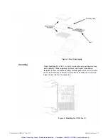
Figure 5: 6U board insertion into system box
Installation of the R.ear Transition Module
The CTM 17 is a 6U x 80 mm rear I/0 module which has to be plugged into the
CR! I separated by the backplane. This tran
s
ition module has a DVI-I
connector. If necessary you need an external adaptor to be fully compatible
with the VGA standard connector and pin outs
.
On the transition module you
either can cow1ect a DVI panel or a standard VGA Monitor
,
but not both a.t the
same time.
Plug your video monitor into this collllector. Make sure that your selected
chassis supports this type of rear I/0 transition module.
After making sure that you have in
s
talled the CR! I properly into your CPCI
bacl..'Plane, a
p
p
l
y
power to your video monitor and then the CPCI supply. When
the board is completely reset
,
the processor
s
hould begin executing initial
BIOS-resident routines.
Note:
Make sure that the card ejectors are closed and the Hot Swap LED
(
bl
u
e
)
is
OFF
.
Note:
If the CR! I was ordered without video on board, you can use an external video
CompactPCI card or a video PMC module
.
Consult the teclutical descriptions
of these boards for required voltage and power consumption in the system.
Artisan Technology Group - Quality Instrumentation ... Guaranteed | (888) 88-SOURCE | www.artisantg.com

